In this post, I’ll walk you through how to use the ESP8266 web server in Proteus in a simple and practical way. If you’ve been following my earlier posts, you already know that I’ve covered ESP8266 simulation in Proteus with different features and examples. This guide builds on that and takes things a step further.
Below, I’ve also included a list of my ESP8266 Proteus simulation guides. If you haven’t checked them out yet, it’s worth going through them, they’ll help you understand the overall setup and make this guide easier to follow.
ESP8266 Web Server
The ESP8266 model comes with a built-in HTTP server that’s actually quite powerful. It can handle request parsing, manage routes, and supports keep-alive connections, so it behaves pretty close to a real device. Once you start it on port 80, it can instantly serve a ready-made responsive dashboard, or you can replace it with your own custom web page if you want more control over the interface.
Another useful feature is the availability of dedicated GET and SET endpoints. These allow you to directly read from and control GPIO pins using simple GET or POST requests, which makes testing and integration a lot easier, especially when you’re simulating real-world scenarios.
How to Start Simulating the ESP8266 Web Server
If you’ve read the introduction post of the ESP8266 simulation model, you’ll remember that I listed all the AT commands supported by the model. For this setup, we only need a few basic commands to activate the ESP8266 web server functionality. To keep things simple, we’ll do this without using any microcontroller. Instead, we’ll use the Virtual Terminal in Proteus to communicate directly with the ESP8266 model.
After starting the simulation, type AT and press Enter to check if the module is responding. If everything is working correctly, you should get an OK response. For a better experience, enable the “Echo typed characters” option in the Virtual Terminal so you can see the commands you type.
Next, enter the following command to set the WiFi mode to Access Point (AP):
AT+CWMODE=2You should receive an OK response. After that, enable multiple TCP connections with:
AT+CIPMUX=1Again, you should see OK if the command is successful. Now, start the web server on port 80 using:
AT+CIPSERVER=1,80Once you receive the OK response, the ESP8266 web server will be running on your local machine at 127.0.0.1.
Optionally, you can use the following command to reduce clutter in the terminal:
AT+WEBQUIET=1This hides the +IPD messages while browsing, making the output cleaner.
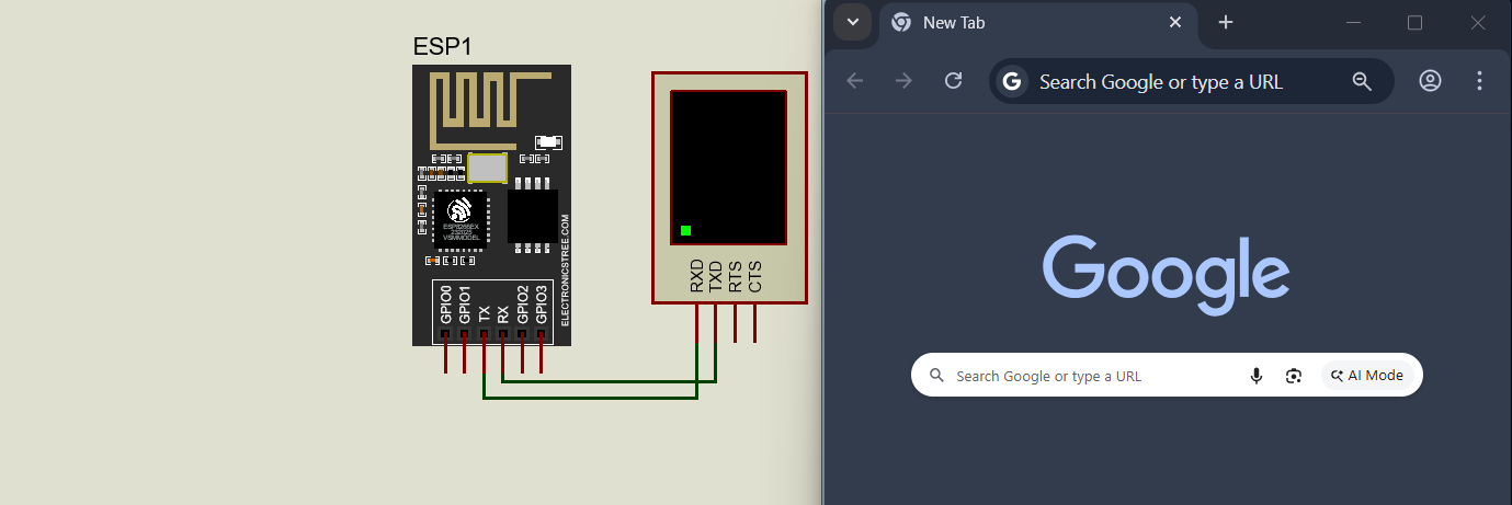
Finally, open your web browser and go to 127.0.0.1. You should now be able to access the web interface and control the ESP8266 directly from your browser.
Controlling the GPIO Pins
The model includes four fully functional GPIO pins, and each one can be configured as either an input or an output. Any changes are detected instantly and reflected on the web interface in real time. You can control the pins directly from the web page or by using HTTP commands, and the updates will immediately appear in the Proteus schematic. This gives you smooth, real-time bidirectional control without any noticeable delay.
By default, all pins are set as input. Once you start the ESP8266 web server, you’ll be able to see the pin state changes live on the web page.
If you want to configure a pin as an output, you can use the following command:
AT+GPIOMODE=<pin>,<0/1>Here, 0 sets the pin as input and 1 sets it as output. The available pins range from 0 to 3, so you can configure them according to your needs.
You can set the GPIO pin mode at any time, there’s no need to switch the ESP8266 into a specific mode or apply extra settings. If you prefer, you can even configure the pins after the web server has already started.
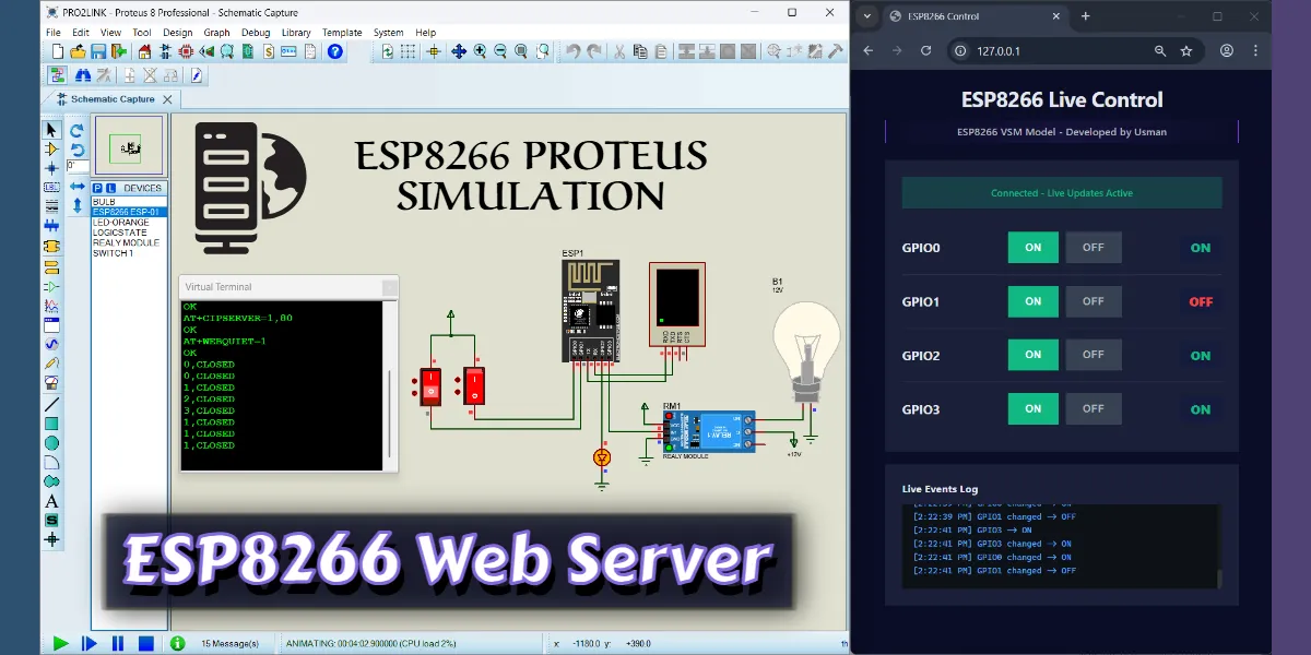
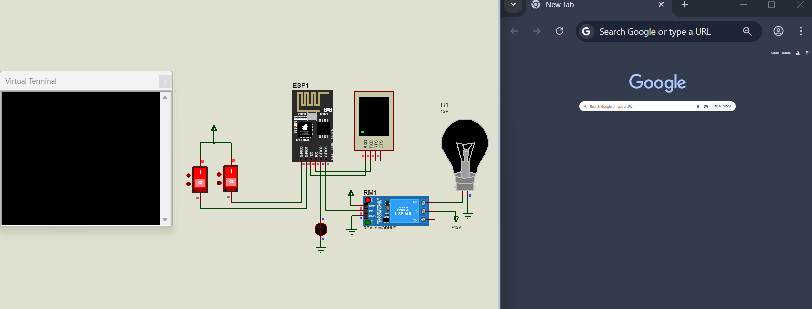
For this example, I first set pins 3 and 2 from input to output, and then started the ESP8266 web server. In the image, you can see that both pins are configured as output before the server is running. I’m using these pins to control a relay module with a bulb and a simple LED.
From the web page, you can turn these pins ON or OFF using buttons. At the same time, the states of the other pins (used as input) are also displayed on the web interface. In my setup, those input pins are connected to switches, so you can monitor their status live.
That’s it for this guide. You should now have a clear idea of how to set up and use an ESP8266 web server in Proteus for your own simulation projects. If you run into any issues, feel free to leave a comment and I’ll help you out.
In the next post, I’ll show you how to create and load your own server files into the ESP8266 web server, so you can use a custom web page instead of the default one.
Join the official WhatsApp channel of ElectronicsTree to stay updated with the latest electronics tutorials, Proteus libraries, Arduino projects, and simulation resources.

