The TCS3200 Proteus library has been one of the most requested components in the Proteus community, and now it’s finally available. I’ve created this model and made it free to download, along with a complete guide on how to use it in your simulations.
This model represents the behavior of the TCS3200 color light-to-frequency converter inside Proteus, allowing you to work with it directly in your circuits without needing physical hardware. It runs with an interactive interface during simulation, where you can select any RGB color using the Windows color picker, adjust light intensity with a slider, and see the changes update instantly in real time.
In this post, I’ll also walk you through how to set it up and use it properly in your projects.
How the Real TCS3200 Works
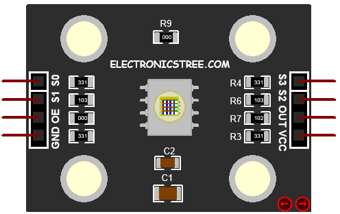
Before diving into the model, it helps to understand what the real chip does. The TCS3200 contains an 8×8 array of 64 photodiodes. Each photodiode is covered by one of four filter types red, green, blue, or clear (no filter) with 16 photodiodes per type. The chip uses a built-in current-to-frequency converter: the more light hits the active photodiodes, the higher the output frequency on the OUT pin.
The output is always a square wave with a 50% duty cycle. The frequency is directly proportional to the light intensity detected through the currently selected filter. You select which set of photodiodes is active using the S2 and S3 pins, and you can scale the output frequency range using S0 and S1.
By sequentially selecting each filter (Red – Green – Blue), reading the output frequency for each, and comparing the three values, your microcontroller can determine the color of the object being sensed.
TCS3200 Proteus Library Model
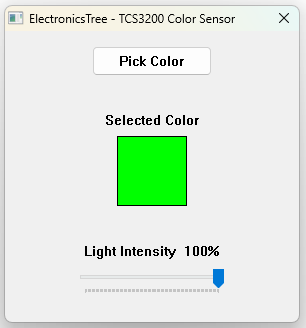
When the simulation starts, a small floating window appears (you can also hide or show it using the arrow buttons). This window acts as the main control panel for the model and includes two controls:
Pick Color Button
Clicking Pick Color opens the standard Windows color picker dialog. You can enter exact RGB values or click anywhere on the color spectrum. Once you confirm your selection, the color is immediately applied to the simulation, the colored rectangle in the window updates, and the OUT pin frequency changes accordingly on the very next simulation callback.
The color you pick represents the object color (or light color) that the sensor is “seeing.” For example, picking pure red (R=255, G=0, B=0) means:
- The red filter channel will output a high frequency (bright)
- The green and blue filter channels will output a very low frequency (dark)
Light Intensity Slider
The slider at the bottom of the window controls an overall light intensity multiplier, from 0% to 100%. This simulates how much ambient or reflected light is reaching the sensor, independent of color.
- 100%: full brightness; colors are read at their full RGB values
- 50%: all channel intensities are halved, frequencies drop accordingly
- 0%: no light; output frequency drops to zero on all channels
This is useful for testing how your firmware handles low-light conditions or for simulating a sensor that is partially obscured.
Frequency Scaling (S0 / S1)
The S0 and S1 pins together control how the internal output frequency is divided before reaching the OUT pin. This allows you to tune the frequency range to suit your microcontroller’s measurement capability.
| S0 | S1 | Output Frequency Scaling |
|---|---|---|
| LOW | LOW | Power-down: output held LOW, no pulses |
| LOW | HIGH | 2% of full scale (max ~10 kHz) |
| HIGH | LOW | 20% of full scale (max ~100 kHz) |
| HIGH | HIGH | 100% full scale (max ~500 kHz) |
Recommendation for most microcontrollers: Use 20% scaling (S0=HIGH, S1=LOW). This gives a maximum output of ~100 kHz, which is comfortably within the measurement range of most 8-bit and 32-bit microcontrollers using standard timer-based frequency counting or pulse-width measurement.
When to use 2% scaling: If your microcontroller runs at a low clock speed or you are using a software-based measurement approach, 2% scaling gives slower, wider pulses that are easier to time accurately.
When to use 100% scaling: Useful if you need the highest resolution and are using hardware timers or interrupt-driven measurement on a fast MCU.
Power-down mode (S0=LOW, S1=LOW): The model drives the OUT pin LOW and re-checks the pins every 1 µs of simulation time. No pulses are generated. Use this to save simulated power or when the sensor is not needed
Filter Selection (S2 / S3)
The S2 and S3 pins select which set of photodiodes, and therefore which color filter, is active. Only one filter can be active at a time.
| S2 | S3 | Active Filter | What It Measures |
|---|---|---|---|
| LOW | LOW | Red | Intensity of red light component |
| HIGH | HIGH | Green | Intensity of green light component |
| LOW | HIGH | Blue | Intensity of blue light component |
| HIGH | LOW | Clear | Broadband intensity (no color filter) |
How to Extract RGB Data from a TCS3200 Proteus Library Model
To get a full RGB reading, your microcontroller must perform three sequential measurements:
- Set S2=LOW, S3=LOW → measure frequency → this is your red reading
- Set S2=HIGH, S3=HIGH → measure frequency → this is your green reading
- Set S2=LOW, S3=HIGH → measure frequency → this is your blue reading
A short settling delay (typically 5-50 ms) between switching filters and taking a measurement is recommended, allowing the output frequency to stabilize after the filter change.
Clear Channel
The clear (no filter) mode, S2=HIGH S3=LOW, passes all visible wavelengths. In this model it is simulated as the average of the red, green, and blue values, a broadband approximation. It is useful as a reference for normalizing the RGB readings against overall ambient brightness.
Output Signal Behavior of the TCS3200 Proteus Library Model
The OUT pin produces a continuous square wave with a 50% duty cycle whenever the sensor is not in power-down mode. The frequency encodes the light intensity of the currently selected channel:
Output Frequency = (Channel Intensity / 255) × 500,000 Hz × Scaling FactorWhere:
- Channel Intensity is the 0-255 value of the selected color (R, G, or B) multiplied by the light intensity slider percentage
- 500,000 Hz is the full-scale frequency matching the TCS3200 datasheet
- Scaling Factor is 0.02, 0.20, or 1.00 depending on S0/S1
Example
You select the color R=128, G=128, B=255 in the GUI, intensity slider at 100%, and S0=HIGH, S1=LOW (20% scaling):
| Channel | Intensity | Frequency | Half-period |
|---|---|---|---|
| Red (S2 = L, S3 = L) | 128 | ~50,196 Hz | ~9.96 µs |
| Green (S2 = H, S3 = H) | 128 | ~50,196 Hz | ~9.96 µs |
| Blue (S2 = L, S3 = H) | 255 | ~100,000 Hz | ~5.0 µs |
Noise
The model adds a small ±5% random noise to each frequency output. This mimics the real sensor’s measurement variation and prevents the output from being artificially perfect. Your firmware should account for this by averaging multiple readings.
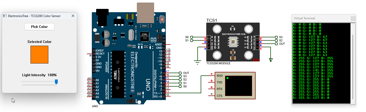
Interfacing TCS3200 Proteus Library Model with Arduino
The TCS3200 doesn’t give RGB values directly, it outputs a frequency based on the detected color. This code reads that frequency and converts it into usable RGB values (0–255). S2 and S3 are used to select Red, Green, or Blue filters, and the OUT pin gives the pulse signal. The readChannel() function switches the filter, takes multiple pulse readings using pulseIn(), and averages them for stability.
The toValue() function then converts the pulse width into a 0–255 range, where shorter pulses mean brighter color. In the loop, the code reads R, G, and B one by one, converts them, and prints the values to the serial monitor.
Arduino Code
#define PIN_S0   3
#define PIN_S1   4
#define PIN_S2   5
#define PIN_S3   6
#define PIN_OUT  7

// Calibration
// WHITE: intensity=255, 20% scale → freq=100 kHz → half-period = 5 µs
// BLACK: intensity=0 → freq=0 → pulseIn returns 0 → handled separately
// TIMEOUT: anything slower than ~2 Hz (half-period > 250,000 µs) is treated as black
#define CAL_WHITE_US   5UL
#define PULSE_TIMEOUT  50000UL

// Samples per channel
#define SAMPLES  5

// readChannel — select filter, wait, average SAMPLES pulses
// Returns average half-period in µs, or 0 if black/timeout
unsigned long readChannel(bool s2, bool s3)
{
    digitalWrite(PIN_S2, s2);
    digitalWrite(PIN_S3, s3);
    delay(10);

    unsigned long total = 0;
    uint8_t valid = 0;

    for (uint8_t i = 0; i < SAMPLES; i++)
    {
        unsigned long pw = pulseIn(PIN_OUT, HIGH, PULSE_TIMEOUT);
        if (pw > 0)
        {
            total += pw;
            valid++;
        }
    }

    return (valid > 0) ? (total / valid) : 0;
}

// toValue — convert half-period (µs) to 0–255
int toValue(unsigned long pulseUs)
{
    if (pulseUs == 0) return 0;
    if (pulseUs <= CAL_WHITE_US) return 255;

    unsigned long freq = 500000UL / pulseUs;
    int val = (int)((unsigned long)freq * 255UL / 100000UL);

    if (val < 0) val = 0;
    if (val > 255) val = 255;

    return val;
}

void setup()
{
    pinMode(PIN_S0, OUTPUT);
    pinMode(PIN_S1, OUTPUT);
    pinMode(PIN_S2, OUTPUT);
    pinMode(PIN_S3, OUTPUT);
    pinMode(PIN_OUT, INPUT);

    digitalWrite(PIN_S0, HIGH);
    digitalWrite(PIN_S1, LOW);

    Serial.begin(9600);
    Serial.println("TCS3200 ready.");
    Serial.println();
}

void loop()
{
    // S2=L,S3=L → Red
    // S2=H,S3=H → Green
    // S2=L,S3=H → Blue
    unsigned long rawR = readChannel(LOW, LOW);
    unsigned long rawG = readChannel(HIGH, HIGH);
    unsigned long rawB = readChannel(LOW, HIGH);

    int r = toValue(rawR);
    int g = toValue(rawG);
    int b = toValue(rawB);

    Serial.print("R: "); Serial.print(r);
    Serial.print(" G: "); Serial.print(g);
    Serial.print(" B: "); Serial.print(b);
    Serial.println();

    delay(500);
}
Download Library
Simply click on the button to download the library. You can refer to this post for instructions on how to install the library in Proteus 8. How to Download and install Library in Proteus (electronicstree.com)
ZIP Password : electronicstree.com
We’re always looking to expand our library collection based on what our community needs. If you’re looking for a specific Arduino module, sensor, or component that we don’t currently offer, we’d love to hear from you!
Reach out to us at help@electronicstree.com with your requests. We prioritize new library development based on community demand, so your suggestion could be our next addition.
Join the official WhatsApp channel of ElectronicsTree to stay updated with the latest electronics tutorials, Proteus libraries, Arduino projects, and simulation resources.