
This is the second part of the GUI design for Arduino series, aimed at teaching processing methods in the easiest way possible to create a user-friendly GUI. In the first part, we developed an application that provides a GUI for establishing serial connections. It includes a drop-down menu for selecting the serial port and baud rate, as well as buttons for establishing and disconnecting from the port.
📃Interested In Designing GUI For Arduino? Easy Guide For Beginners – Processing4
GUI Design for Arduino - PART2
In this part, we will send data from our app to Arduino. There are various GUI elements that can be used for this purpose, but we will utilize a text field and a button. Initially, we will gather text data from the user via the text field. Subsequently, we will use the button to send the data. Let’s first grasp how we can create a text field using the text field controller.
Text Field Demo:
Let’s summarize the process of creating and using GUI elements in ControlP5 using the text field demo. The purpose of repeating this method is to remember how to create a GUI using the ControlP5 library. This method applies to every GUI element you want to create using ControlP5.
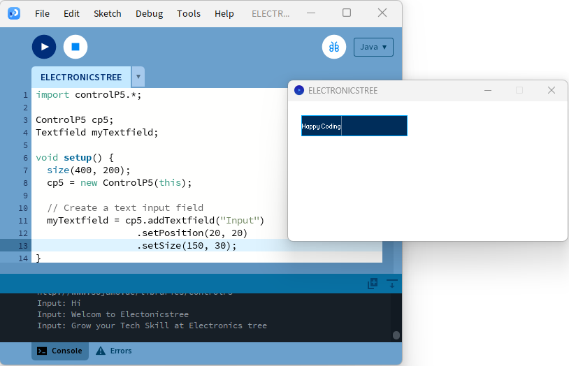
Before you can create a GUI element, such as a text field, you need to declare an object of the relevant controller type. For example:
Textfield myTextfield; Inside the setup() function, use the relevant controller’s methods to create the GUI element. For a text field, you would use addTextfield():
myTextfield = cp5.addTextfield("Input")

.setPosition(20, 20)

.setSize(200, 40);
To handle events or input from the GUI element, you create a callback function. In the case of a text field, you can create a callback function that receives the text input when the user interacts with the text field. For example:
void Input(String theText) {

println("Input: " + theText);

}
Ensure that the callback function has the correct signature to match the controller’s event (e.g., for a text field, it should receive a String parameter).
Here is the complete example:
Sending Data from GUI App to Arduino
We will integrate the above code with our previous code, excluding the callback function. When combining the codes, we will obtain a text field for data input. The reason for not including the callback function for the text field is that we intend to control this field with another button for sending the data. We will utilize the callback function of the send button for both the button and the text field.
First, add the objects for the Button and TextField methods.
Button sendButton;

Textfield textField;
In the setup function, include the addButton and addTextfield methods to add the button and text field on the screen.
sendButton = cp5.addButton("SendButtonPressed")

.setPosition(270, 250)

.setSize(70, 20)

.setLabel("Send");
textField = cp5.addTextfield("InputText")

.setPosition(50, 250)

.setSize(200, 20)

.setAutoClear(false);
For handling the send button and text field data events, we will use only one callback function.
void SendButtonPressed() {

if (isConnected) {

String data = textField.getText();

myPort.write(data);

println("Sent:", data);

} else {

println("Not connected to any port.");

}

}
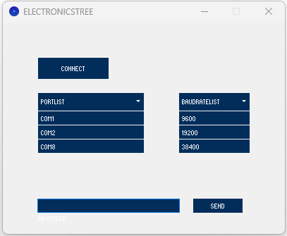
The SendButtonPressed() function sends data from text field over the serial port if connected, printing a confirmation message. If no connection is established, it alerts that no port is connected. Here is the full code (with the previous code – First Part )
Now, let’s write code for Arduino to test our app. Here is the simple Arduino code which receives the text command from Processing and turns the LED on and off accordingly.
Here is the result:
Receiving Data form Arduino
The Serial library in Processing provides functions like read(), readString(), readBytes(), and readStringUntil() for reading data from a serial port. These functions allow you to read bytes, strings, and arrays of bytes, as well as specify delimiters for reading data until a certain character is encountered.
Processing follows an event-driven programming model. This means that certain functions are automatically called when specific events occur. like The serialEvent() function in Processing is a special function that is automatically called whenever new data is available on the serial port that Processing is listening to. Its purpose is to handle incoming serial data in real-time without blocking the main execution of your sketch.
We will receive the data from the serial port using the serialEvent() function.
void serialEvent(Serial myPort) {

String data = myPort.readStringUntil('\n');

if (data != null) {

data = data.trim();

println(data);

}

}
Within this function, the line String data = myPort.readStringUntil('\n'); reads a string of characters from the serial port until a newline character ('\n') is encountered, and this string is stored in the variable data. The subsequent if (data != null) statement checks if the read data is not null, indicating that valid data has been received. If the data is valid, the line data = data.trim(); removes any leading or trailing whitespace characters from the string, ensuring it is clean. Finally, println(data); prints the cleaned data to the console. Here is the result:
Creating the Text Area:
We get data from Arduino, and right now, it shows up on the console. But we want it on our app’s screen. So, we’ll add a text area to our app and display the data there instead.
In Processing, the ControlP5 library provides functionality to create and manage text areas within sketches. A text area is a graphical user interface component used for displaying and potentially editing multiline text within a window or interface.
You can create a Textarea object, adjust its properties like position, size, font, and colors, and then include it in your sketch (similar to the other GUI elements we made with controlP5, so I won’t repeat the steps here). Below is a simple example of how you can utilize the Textarea component.
I have adjusted some parameters of the text area to suit our app.
myTextarea = cp5.addTextarea("ReceivedText")
.setPosition(50, 300)
.setSize(300, 80)
.setFont(createFont("Roboto", 14))
.setLineHeight(14)
.setColor(color(255))
.setColorBackground(color(56))
.setScrollBackground(color(100));
To showcase the received data in the Textarea, you can adjust the serialEvent function to add the received data to the Textarea. For this, you need to replace the line of code println(data); with receivedText.append(data + “\n”);
void serialEvent(Serial myPort) {

String data = myPort.readStringUntil('\n');

if (data != null) {

data = data.trim();

receivedText.append(data + "\n");

}

}
Converting the Text Area into Console:
While exploring the ControlP5 library, I came across an example that demonstrates how to turn your text area into a console. By connecting the text area with the console, any output generated by println() will be directed to the text area instead of the default console.
This is achieved by using the addConsole() method provided by ControlP5, which takes a textarea as an argument. Here’s a basic example of how to use a textarea as a console in Processing with ControlP5:
A Basic GUI Design for Arduino - Final Result
Now we can use this method in our app code. It’ll give us a good console to show data received from Arduino, and it’ll also display any debug messages we print using println.
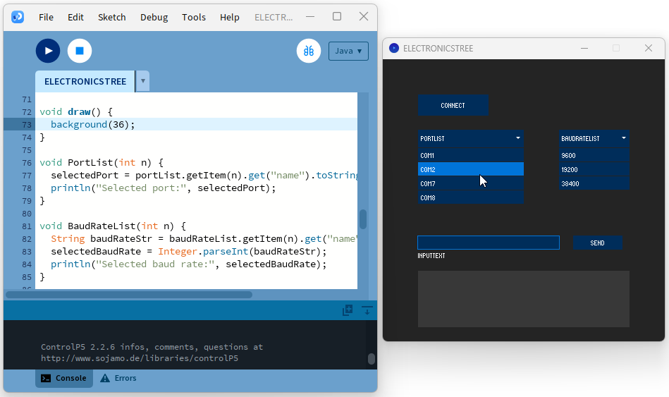
At this stage, our Processing sketch appears excellent for handling serial communication with an Arduino board! It incorporates a GUI design for Arduino for selecting the serial port and baud rate, connecting/disconnecting, sending data, and displaying received data. Moving forward, we plan to further enhance our GUI elements and introduce additional controls for better Arduino management.