
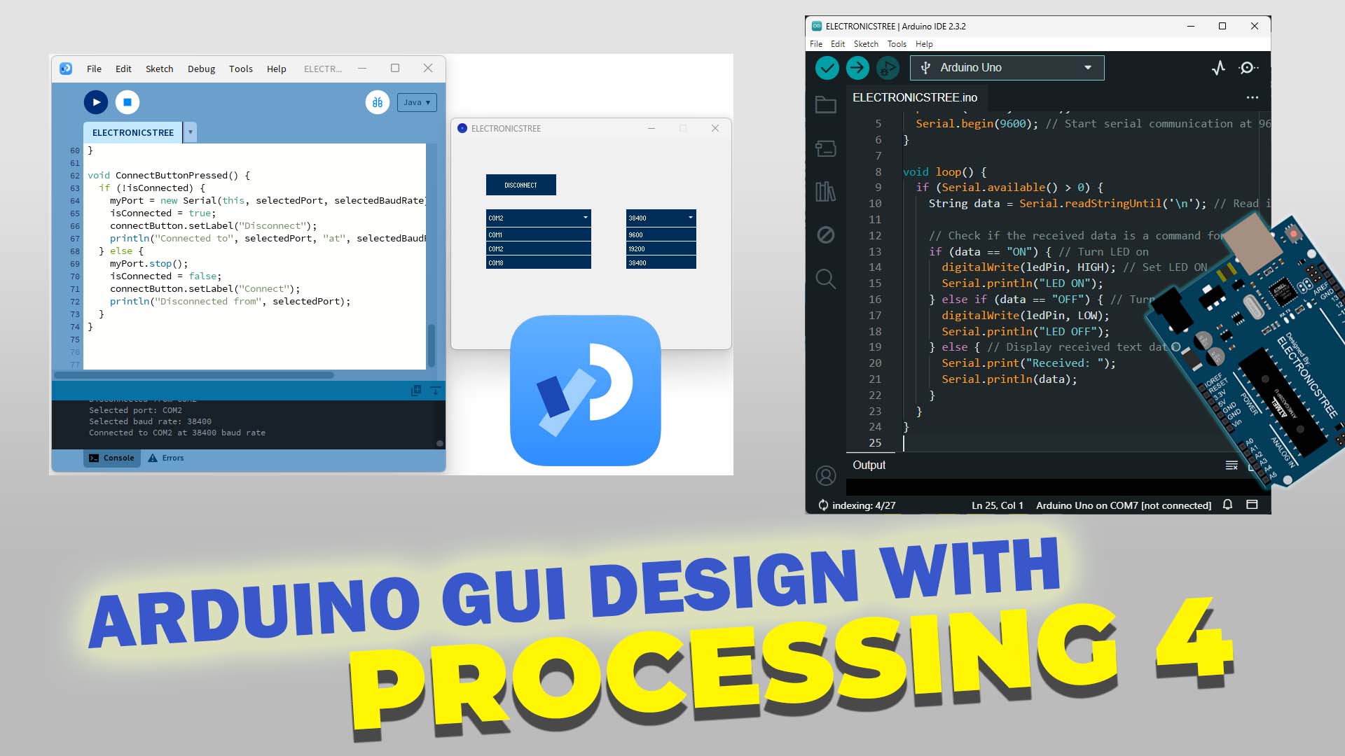
Welcome to our beginner’s guide to crafting GUI for Arduino using Processing4! Here, we’ll take you step-by-step through the process of designing interactive interfaces for your Arduino projects. Whether you’re just starting out or already have some experience with Arduino and Processing, this tutorial is crafted to be easy to understand and follow. By the end, you’ll be equipped with the knowledge and confidence to develop your own personalized GUIs that seamlessly complement your Arduino setups.
GUI for Arduino
Using GUI for Arduino involves creating graphical interfaces that allow users to interact with Arduino projects visually. By designing GUIs, users can control and monitor Arduino devices using buttons, sliders, and other graphical elements instead of relying solely on text-based interfaces. This simplifies the user experience and makes it more intuitive, especially for beginners or those unfamiliar with coding. GUIs for Arduino can be created using software tools like Processing or libraries such as TFT or Nextion.
How to start designing GUI for Arduino
To begin designing GUI for Arduino, you’ll need some basic tools and software. First, choose a platform for creating your GUI, such as Processing, which is commonly used for its simplicity and compatibility with Arduino.
Processing 4
- Visit the official Processing website: 🔗processing.org
- On the download page, you’ll see options for different operating systems such as Windows, macOS, and Linux.
- Click on the download link corresponding to your operating system.
When you download Processing, it typically comes as a compressed ZIP file. After downloading, you’ll need to unzip this file. Once unzipped, you’ll have a directory containing the Processing executable. On Windows, this executable is usually named “processing.exe”. To run Processing, simply double-click on the “processing.exe” file. This will launch the Processing editor, where you can start creating your GUI designs for Arduino.

I have already created a video on Arduino and Processing. The first part covers establishing serial communication between Arduino and Processing. Now, I’ll discuss the serial library available in Processing and demonstrate how to connect with Arduino via GUI design.
Processing Serial Library - How to use it
The Serial library comes built-in with Processing! You don’t have to install anything extra to use it for talking to Arduino or other serial devices.
Obtaining Serial Port:
Importing the Library: First, you need to import the Serial library at the top of your Processing sketch. You can do this by adding the following line:
import processing.serial.*; We want to design the GUI for Arduino, so the first step is connecting the Arduino with Processing using the serial port. First, let’s check how many ports are available on my PC. You can do this by using a function called Serial.list(). This function basically gives you a list of all the serial ports that are currently accessible.
import processing.serial.*;
void setup() {
printArray(Serial.list());
}
Inside the setup() function, this line calls the Serial.list() function, which returns an array of strings containing the names of all available serial ports on the computer. Then, the printArray() function is used to display this array in the console. This allows you to see a list of available serial ports and choose the appropriate one for communication with an Arduino or other serial device.
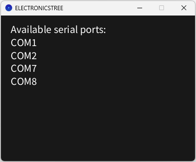
The output of this code would look something like this:
[0] "COM1"
[1] "COM2"
[2] "COM7"
[3] "COM8"
Display of Serial Ports on the Screen:
It’s much easier in Processing! With just three lines of code, you can obtain the list of COM ports available on your PC. Now let’s move forward and display these available ports as text on the screen instead of the console. Processing provides the text() function for displaying text on the screen. Therefore, we utilize this function to display the available ports on the screen.
After importing the serial library, we use the setup function. The setup() function is called once when the sketch starts. Within this function:
- We set the size of the canvas to 400 pixels wide and 300 pixels tall using
size(400, 300). - The background color of the canvas is set to a shade of gray using
background(24). - We use the
Serial.list()function to retrieve an array of available serial ports on the system. - A string variable
portsTextis initialized to hold the text to be displayed on the screen. - We loop through the
portsarray and concatenate each port name with a newline character toportsText. - Text alignment is set to left-aligned and starts from the top-left corner using
textAlign(LEFT, TOP). - The text size is set to 22 pixels using
textSize(22). - Finally, we use the
text()function to display theportsTexton the screen with a margin of 20 pixels from each side.
This Processing code creates a simple application that displays the available serial ports on your system.
How to make Serial Connection:
We’ve learned about the Serial library method (Serial.list()), enabling us to retrieve ports. Now, we can employ the Serial class constructor to establish connections with them, creating an instance of the Serial class using the Serial() constructor.
Serial(parent, portName, baudRate)
The parameter ‘parent’ typically utilizes the ‘this’ keyword, while the other two parameters, ‘portName’ and ‘baudRate’, indicate their respective functions. ‘portName’ specifies the port to which we intend to connect, while ‘baudRate’ denotes the baud rate of this port.
myPort = new Serial(this, "COM1", 9600);
This command will establish a connection to COM1 with a baud rate of 9600. after that you can write the data to the serial port using myPort.write(data). here is the basic example:
import processing.serial.*;
Serial myPort;
void setup() {
myPort = new Serial(this, "COM1", 9600);
}
void draw() {
myPort.write(65);
}
So, the code continuously sends the character ‘A’ (represented by the byte value 65) to the serial port “COM1” at a baud rate of 9600.
Now, instead of just showing the available serial ports as text or typing them manually in the serial constructor, we’ll use GUI elements. We’ll make a dropdown menu for the ports and add a button to connect to them. To do this, we’ll use the ControlP5 library. This is where we start; we’ll learn more advanced GUI techniques later.
GUI for Arduino with ControlP5 Library
ControlP5 🌐 is a library for Processing that provides a set of GUI (Graphical User Interface) components. It allows you to easily create interactive elements such as buttons, sliders, dropdown lists, checkboxes, and text inputs within your Processing sketches.
Button Demo:
In the Processing IDE, navigate to the Library Manager. At the top, there is a search bar. Type “ControlP5” into the search bar and press Enter. You will see ControlP5 listed in the search results. Click on the ControlP5 entry, and then click the “Install” button next to it. Processing will download and install the library for you. Once the ControlP5 library is installed, you can begin using it in your Processing sketches by including the import statement at the top of your code:
import controlP5.*;
Let’s create a simple example that demonstrates the basic usage of ControlP5 with a button. After importing the library, next, you need to create a ControlP5 object in your sketch. This object will manage all the GUI elements you create. Here’s an example:
ControlP5 cp5;
In the setup() function of your sketch, initialize the ControlP5 object:
void setup() {
size(200, 200);
cp5 = new ControlP5(this);
}
Use the addButton() method of the ControlP5 object to create a button. Specify the button’s position, size, and label.
cp5.addButton("buttonName")
.setPosition(50, 50)
.setSize(80, 35)
.setLabel("Click me");
Define a function that will be called when the button is clicked. This function should have the same name as the button’s name.
void buttonName() {
println("Button clicked!");
}
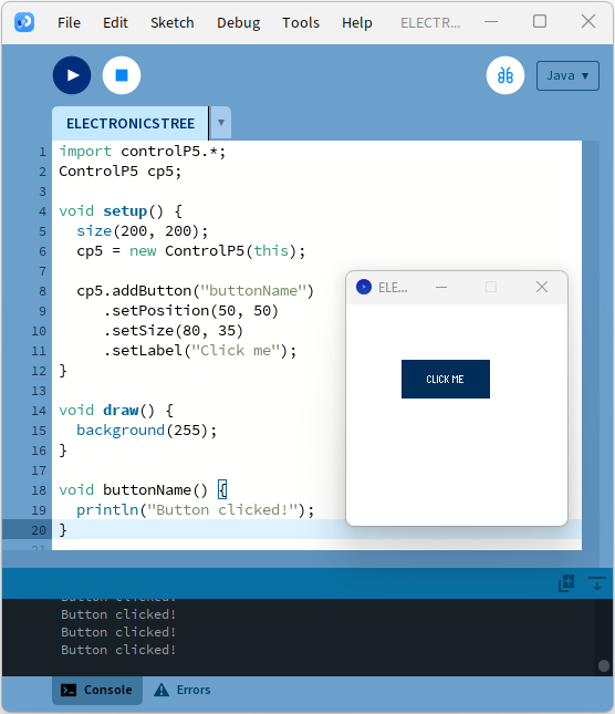
Here’s the complete example:
Here’s the result:
Dropdown Menu Demo:
Now, let’s create a dropdown menu using the scrollable list method provided by ControlP5. Declares a ControlP5 object named cp5, which will be used to manage GUI elements. Declares a ScrollableList object named myList, which represents the scrollable list that will be created.
ControlP5 cp5;
ScrollableList myList;
After setting the sketch window size in the setup function, the ControlP5 object, cp5, is initialized with a new instance of ControlP5, using ‘this’ (the current sketch) as an argument. Following this, a scrollable list named “myList” is created using ControlP5’s addScrollableList method. The position, size, bar height, and item height of the list are then set.
size(400, 400);
cp5 = new ControlP5(this);

myList = cp5.addScrollableList("myList")
.setPosition(100, 100)
.setSize(200, 200)
.setBarHeight(20)
.setItemHeight(20);ScrollableList myList;
Now, we need to create a loop that iterates from 1 to 11 and adds items to the “myList” with labels “Item1” through “Item10,” each with its corresponding index.
 for (int i = 1; i < 11; i++) {
myList.addItem("Item " + i, i);
}
Create a callback function for the dropdown menu selection.
void myList(int n) {
String selectedLabel = myList.getItem(n).get("name").toString();
println("Selected: " + selectedLabel);
}
This callback function triggered when an item is selected from the scrollable list:
- It retrieves the selected port from the list.
- Prints the selected port to the console.
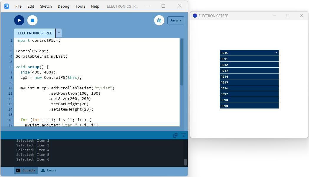
This is the main part of our code, which helps us create the dropdown menu using the scrollable list. Here is the complete code that displays the dropdown menu on the screen.
Here’s the result:
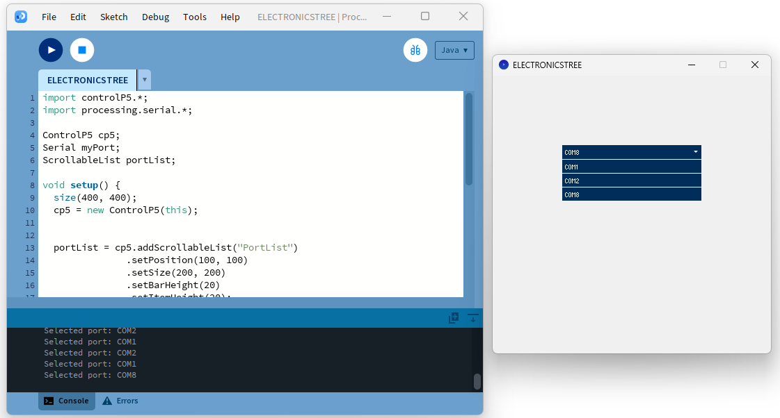
Display COM Ports with Dropdown:
Now, let’s combine our code for displaying serial ports with the code for the dropdown menu to show the ports using the dropdown menu.
Here’s the result:
Serial Connection with GUI:
We’ve made significant progress with the ControlP5 library for designing GUIs for Arduino. We’ve learned how to use this library to create GUI components such as buttons and dropdown menus. We’ve displayed our serial ports in the dropdown menu. Now, the next step in our progress is to add buttons for connecting and disconnecting from the port.
Now, integrate the following lines of code into your previous sketch. (dropdown menu code)
Button connectButton;

boolean isConnected = false;

String selectedPort = "";
First, declare a Button object for connecting and disconnecting. Then, initialize a Boolean variable to track the connection status and another one for an empty string to store the selected serial port.
In the setup function, use the cp5.addButton() method to create a connect/disconnect button, and set its initial label to ‘Connect’.
connectButton = cp5.addButton("ConnectButtonPressed")

.setPosition(100, 50)

.setSize(100, 30)

.setLabel("Connect");
Create a callback function for the Button Action.
void ConnectButtonPressed() {

if (!isConnected) {

myPort = new Serial(this, selectedPort, 9600);

isConnected = true;

connectButton.setLabel("Disconnect");

println("Connected to", selectedPort);

} else {

myPort.stop();

isConnected = false;

connectButton.setLabel("Connect");

println("Disconnected from", selectedPort);

}

}
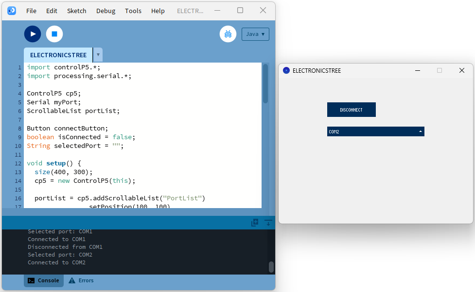
This code handles the “Connect” button press in the GUI. If not already connected (isConnected is false), it establishes a serial connection to the selected port (selectedPort) at 9600 baud rate. It then updates the button label to “Disconnect” and prints a connection message. If already connected, it stops the serial communication, updates the button label to “Connect,” and prints a disconnection message.
Here is the combined code:
Here is the result:
Now, let’s create another GUI element for baud rate selection. For this, we’ll create another dropdown menu using the same scrollable list method that we used for the COM port.
Declare a new ScrollableList variable for baud rate selection.
ScrollableList baudRateList; Create a new variable to store the selected baud rate and set the default value to 9600.
int selectedBaudRate = 9600; In the setup() function, add the baud rate list and include common baud rates. In the case of the COM port, we obtain the list via a function, but in this case, we add the baud rates manually.
baudRateList = cp5.addScrollableList("BaudRateList")
.setPosition(250, 100)
.setSize(100, 100)
.setBarHeight(25)
.setItemHeight(20);
baudRateList.addItem("9600", 9600);
baudRateList.addItem("19200", 19200);
baudRateList.addItem("38400", 38400);
baudRateList.addItem("57600", 57600);
baudRateList.addItem("115200", 115200);
Create a callback function for the dropdown menu selection.
void BaudRateList(int n) {

String baudRateStr = baudRateList.getItem(n).get("name").toString();

selectedBaudRate = Integer.parseInt(baudRateStr

println("Selected baud rate:", selectedBaudRate);
}
In this function, baudRateStr stores the selected baud rate as a string, which is then converted to an integer using Integer.parseInt() before assigning it to selectedBaudRate.
I’ve also made some adjustments to the button and the location of the COM port list on the screen, so now the baud rate list appears next to the COM port list. Here’s the complete example.
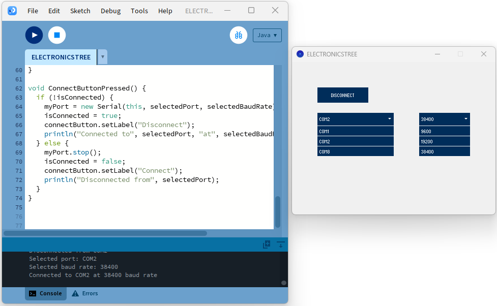
Hurray! Up to this point, we’ve developed a GUI app that offers the necessary elements to connect to the serial COM port with your desired baud rate. Now, in the next part, we’ll send and receive data through serial and enhance our GUI for Arduino to be more customizable and user-friendly.


