Arduino Optical Fiber Transmission Setup
With the previous posts, we have gained a basic understanding of fiber optic communication. In this post, we will create an Optical Fiber Transmission setup and also develop a simulation in Proteus for our circuit. Let’s explore how you can integrate it with an Arduino for various applications.
Optical Fiber Transmission Setup - Transmitter Selection
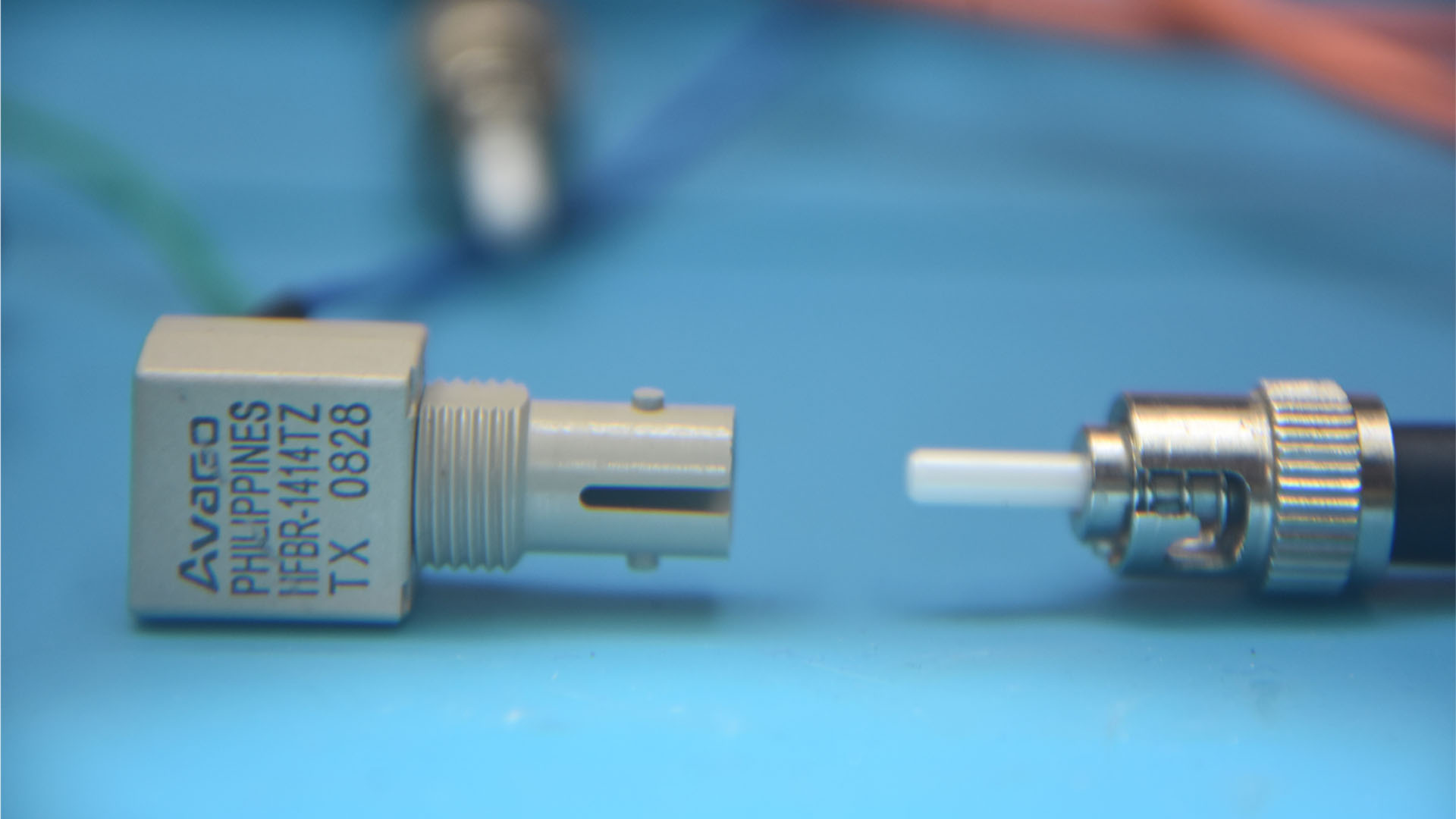
I’m going to use HFBR 1414 fiber optic transmitter module which is manufactured by Broadcom. It is a low-cost high-power transmitter that is designed for use in industrial power generation, power distribution, medical transportation and gaming applications. The HFBR 1414 can transmit data at rates up to 160 megabits over distances of up to 2.7 kilometers. It is compatible with a variety of fiber optic cable types.

Technical Specifications and Compatibility:
The HFBR fiber optic transmitter contains an 820 nanometers aluminum gallium arson emitter capable of efficiently launching optical power into four different optical fiber sizes: 50/125 μm, 62.5/125 μm, 100/140 μm, and 200 μm Plastic-Clad Silica (PCS). This allows the designer flexibility in choosing the fiber size.

Efficiency and Power Consumption Optimization:
The HFBR transmitter is designed with high coupling efficiency, allowing it to operate at low current levels. This results in reduced power consumption and enhances the reliability of the transmitter. For the HFBR-1414Z high-power transmitter, it’s optimized for smaller fiber sizes and can typically emit optical power of -15.8 dBm at 60 mA into 50/125 μm fiber and -12 dBm into 62.5/125 μm fiber.
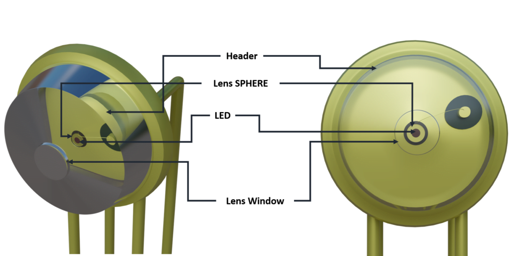
Consistent coupling efficiency is assured by the double-lens optical system. Consistent coupling efficiency reduces receiver dynamic range requirements which allows for longer link lengths.
Optical Fiber Transmission Setup - Cable Selection
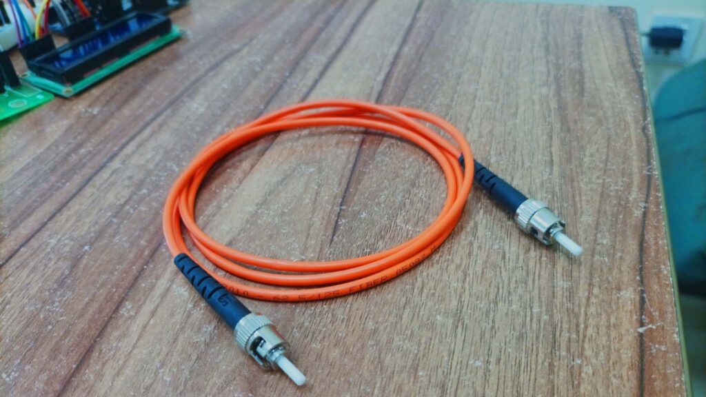
For optical fiber, I’m going to use a multimode fiber optic cable. The core diameter of this cable is 62.5 μm, and the cladding diameter is 125 μm. The cable is equipped with a Straight Tip (ST) connector, which was commonly used in older fiber optic installations.
Optical Fiber Transmission Setup - Receiver Selection
Performance and Compatibility:
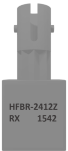
The receiver I am using which is HFBR 2412 is also from Broadcom. the HFBR-2412 is typically used in conjunction with the HFBR-1414 transmitter to create a complete fiber optic communication link. It is a low-cost, high-performance receiver that is designed for use in the same applications as the HFBR transmitter. This receiver can receive data at rates up to 5 megabaud over distances of up to 2 kilometers.
Shared Package Design with HFBR-1414 Transmitter:
It is also compatible with a variety of fiber optic cable types. The HFBR-2412 is housed in the same low-cost, dual-inline package as the HFBR-1414 transmitter. The HFBR-2412 fiber optic receiver module works by converting light signals from an optical fiber into electrical signals. It does this using a photodiode, which is a semiconductor device that generates an electrical current when exposed to light.


Light to Electrical Signal Conversion Mechanism:
The light signal from the optical fiber enters the HFBR-2412 through a lens and is incident on the photodiode. The photodiode generates an electrical current that is proportional to the intensity of the light signal. This electrical current is then amplified and converted into a logic-level signal by the HFBR-2412’s internal circuitry. The HFBR-2412’s output signal is an open-collector Schottky transistor, which can be used to drive a variety of different loads, such as LEDs, relays, and other transistors.
Simple TTL-Compatible Transmitter for Arduino
Analysis of Transmitter Current in Varying Conditions:
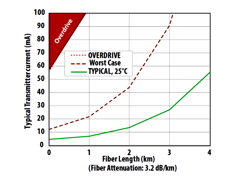
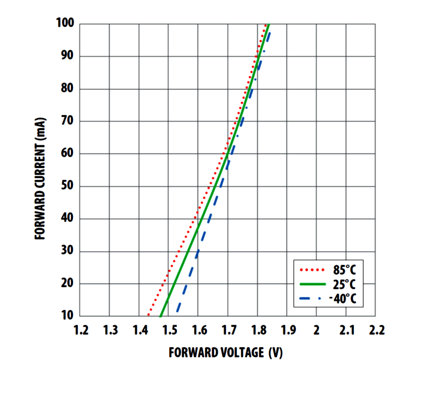
Based on the provided graph, which I obtained from the datasheet, it seems that if your transmitter is operating at a temperature of 25 degrees Celsius (°C) and the cable length is less than 1 kilometer (km), the transmitter current will likely be below 10 mA (milliamperes). You can estimate the exact value by reading the graph where the “TYPICAL, 25°C” curve intersects with the X-axis (Fiber Length). Please note that the graph offers a rough estimate based on the graphical representation, and it doesn’t provide precise numerical values.
Temperature Extremes and Worst-Case Scenarios:
In the worst-case scenario, where the temperature range is -40 to 85°C and the cable length is less than 1 kilometer (km), the transmitter current will probably be below 25 mA (milliamperes). If you choose a maximum distance of 2000 meters using HFBR-1414Z/2412Z logic linked with 62.5/125 μm fiber, the figure shows a worst-case drive current of approximately 43 mA to cover that distance. This means that you can control the distance your signals travel and their clarity by adjusting the transmitter current.
5 MBaud Logic Link Design

Configuring HFBR-1414 Transmitter for Optimal Performance:
Now, let’s discuss how to make the HFBR-1414 Transmitter work with this optical fiber transmission setup to transmit signals. The above figure shows a high-performance, low-cost TTL-compatible transmitter.
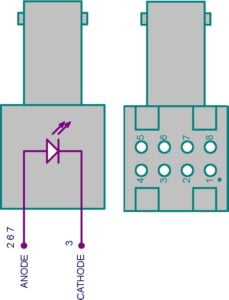
The transmitter has 8 pins, and out of these 8 pins, 4 pins (pin 1, pin 4, pin 5, and pin 8) have no specific connections, but they are electrically connected. Pins 2, 6, and 7 are connected to the Emitter Anode, and pin 3 is connected to the cathode.
Voltage and Current Characteristics Analysis:
The datasheet shows that the forward voltage of this transmitter is typically 1.7V, with a minimum of 1.48V and a maximum of 2.09V. However, if you refer to the Typical Forward Voltage and Current Characteristics graph, it indicates that at 1.5 volts, the transmitter draws 15mA. If you provide the typical 1.7V forward voltage, according to the graph, it requires 60mA. At this current, the transmitter can cover approximately 2.35km in the worst-case scenario with a maximum attenuation of 3.2 dB/km.
Transmitter Circuit Design for Arduino Application:
R1 = (VCC – VF) / IF
R1 = (5V – 1.5V) / 0.015A
R1 = 233Ω
So, setting R1 to 233Ω will result in a drive current of 15mA. I’m going to use the nearest standard resistor value, which is 220Ω. At the typical temperature of 25°C and with 15mA, it can launch -7dB optical power into the fiber cable. However, in the worst-case scenario, the power may be lower.
Power and Distance Considerations:
According to the datasheet, the graph figures are based on theoretical calculations. This means they are derived from mathematical models and are constructed assuming no inline splices or any additional system loss. Should the link consist of any in-line splices, these curves can still be used to calculate link limits, provided they are adjusted for the additional system loss expressed in dB for standard design.
Simple TTL-Compatible Receiver for Arduino
The HFBR-2412 fiber-optic receiver is designed to operate with the 1414 fiber-optic transmitter and 50/125 μm, 62.5/125 μm, 100/140 μm, and 200 μm Plastic-Clad Silica (PCS) fiber-optic cable. The HFBR-2412 receiver incorporates an integrated photo IC containing a photodetector and dc amplifier driving an open collector Schottky output transistor. The HFBR-2412 is designed for direct interfacing to popular logic families. The absence of an internal pull-up resistor allows the open-collector output to be used with logic families such as CMOS requiring voltage excursions much higher than VCC
5 MBaud Receiver
This figure shows the receiver circuit using the HFBR-2412 optical receiver.
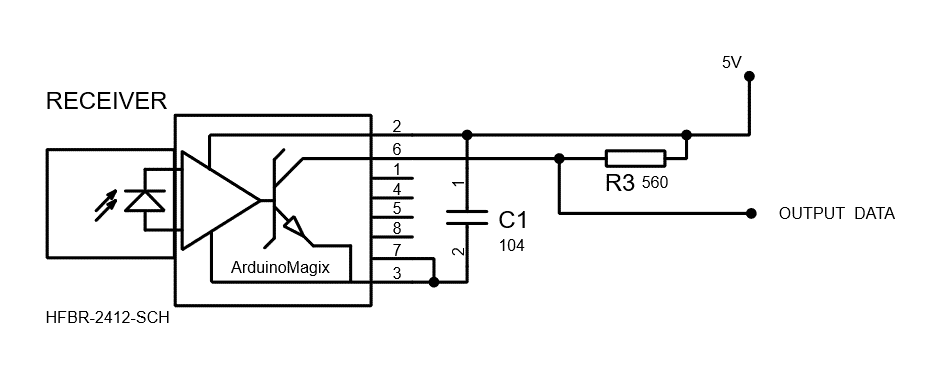
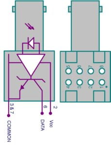
The Receiver also has 8 pins, and out of these 8 pins, 4 pins (pin 1, pin 4, pin 5, and pin 8) have no specific connections, but they are electrically connected. Both the open-collector Data output Pin 6 and VCC Pin 2 are referenced to Com Pins 3 and 7. The Data output allows busing, strobing and wired OR circuit configurations.
Receiver Configuration:
Busing:
This means that the data output can be connected to a data bus, which is a set of wires used to transmit data from one or more sources to one or more destinations. Busing allows multiple devices to share the same data lines, simplifying data transfer in multi-device systems.
Strobing:
Strobing typically involves using a control signal, known as a strobe signal, to synchronize the data output. This can be useful for ensuring that data is transferred or latched at the correct time, preventing data corruption or synchronization issues.
Wired OR Circuit Configurations:
Checkout: Full Video Guide on How Optical Fiber Transmission Setup Works and How you can Transmit Data with Arduino via Optical Fiber Transmission.

Hey! This is fantastic, love the video and your documentation is very thorough. I am wondering how you could adjust the Baud rate, or if its even possible. Specifically, would a 6.2 MBaud be workable, and how would this design be modified to make that possible?
The key point is how the data from the UART is encoded and transmitted over the optical link. The symbol rate in optical communication indicates how many symbols are sent per second. Depending on the modulation scheme, each symbol can carry multiple bits of information.
If the Arduino is sending data at 115200 bps and each bit is directly mapped to a symbol (assuming simple on-off keying), the symbol rate on the optical link will be the same as the data rate from the Arduino. Since 1 baud represents 1 symbol per second, the symbol rate is the same as the baud rate when each bit corresponds to a single symbol.
Thus:
115200 baud = 0.1152 Mbaud