LED Meter Proteus Model Library : Animated Meter with 10 LEDs bar

LED Meter Proteus Model Library : Animated Meter with 10 LEDs bar

You are currently viewing LED Meter Proteus Model Library : Animated Meter with 10 LEDs bar
Led Meter - Proteus Library Models

What is LED METER?

An Animated LED Meter refers to a display or indicator that uses Light Emitting Diodes (LEDs) to visually represent information in a dynamic and animated manner. LED meters are often used to convey data or measurements in a more engaging and easily understandable way. These meters typically consist of a series of LEDs arranged in a linear or circular fashion, and the brightness or color of the LEDs changes to represent different levels or values.

LED Meter Model for Proteus.

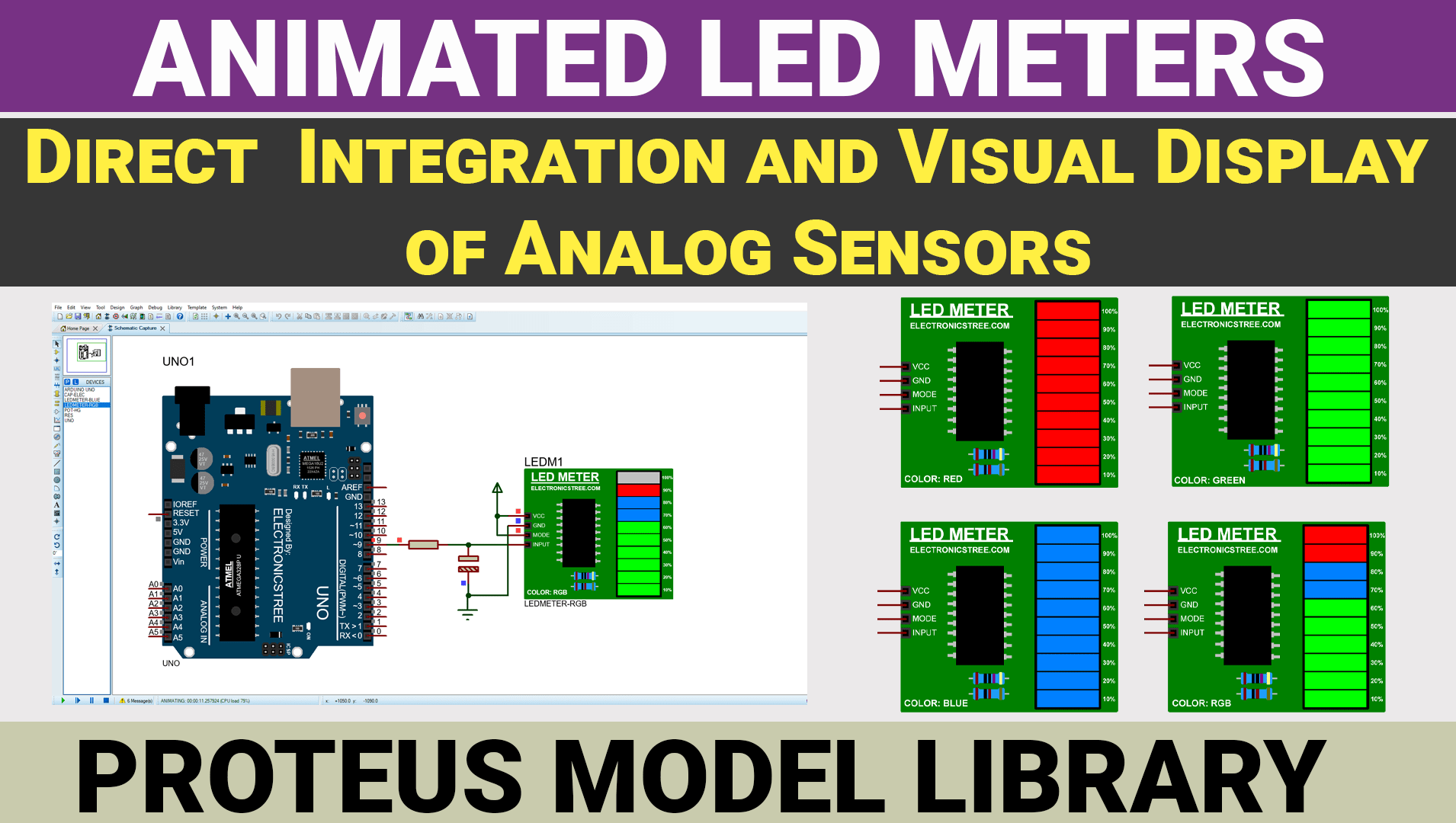
I have developed an LED meter capable of reading voltage ranging from 0 to 5. It features 10 LEDs that correspond to the input voltage level. The goal is to provide a quick and intuitive visual representation of the data, making it easier for users to interpret and respond to changes.

led meter
Led Meter

Difference between LED meter model and Proteus LED bar graph model:

The Proteus LED bar graph display has 10 separate LEDs, each of which can be controlled independently. When you connect it to a circuit, you need to use 10 pins. While it’s okay for small projects, it might not be the best choice for bigger ones because it uses up a lot of pins. The LED meter model I have designed is a linear indicator model that only requires one pin to control all LED segments. Each LED corresponds to a specific voltage range or increment.

LED Meter Display Mode: Based on LM3914

The LED Meter, which uses the LM3914 IC, is a single chip that can detect analog voltage levels and light up 10 LEDs to show a linear display. It also has a feature that lets you choose between showing a moving dot or a bar graph with just one pin.

A short Introduction of LM3914 Display Driver:

As mentioned earlier, the LM3914 is a handy integrated circuit that can drive LEDs, LCDs, or vacuum fluorescents. It allows users to easily switch between bar or dot display modes. It can handle displays of up to 100 steps and operates with a single supply of less than 3V. Its inputs can work all the way down to ground, and you can adjust the output current without needing extra resistors. This IC guarantees reliable performance without multiplex switching or output interference. Plus, it can handle input voltages up to ±35V without any damage or false outputs. With its current-regulated, open-collector LED driver outputs, it can easily connect to TTL or CMOS logic.

Display colors.

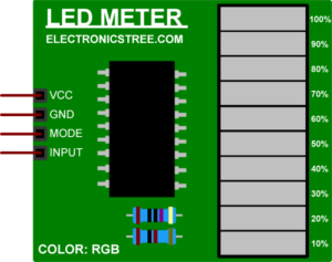
The LED Meter model library consists of four types of meter models: red, green, and blue, with the fourth model being the RGB model. All models have the same functionalities but feature different color displays.

Led Meters
Different Colors Display

How to Use it.

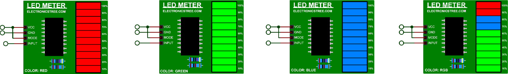
The LED meter is an analog-controlled model that typically expects a real analog voltage input to control the LED brightness or display level. When you connect a potentiometer to the meter input pin, you’re providing a variable analog voltage based on the potentiometer’s position. As you turn the potentiometer knob, it changes the voltage smoothly, which the LM3914 can interpret correctly to adjust its LED outputs accordingly.

If you connect an Arduino PWM pin to the Meter signal pin, the LM3914 receives a rapidly changing signal that it can’t interpret correctly. As a result, it may not work as expected, and the LED outputs may not behave as you intend.

To obtain a real DC (Direct Current) value from a PWM (Pulse Width Modulation) signal, you can use a low-pass filter. Here’s how you can do it:

Use a Low-Pass Filter:

  • A low-pass filter is a circuit that allows low-frequency signals (like DC) to pass through while attenuating higher frequencies (like the PWM frequency).
  • By filtering the PWM signal through a low-pass filter, you can smooth out the pulses to obtain a DC voltage proportional to the duty cycle

Components for the Low-Pass Filter:

  • You’ll need a few components for the low-pass filter, such as resistors and capacitors.
  • The values of these components will depend on the specific PWM frequency, desired cutoff frequency, and load requirements.

Circuit Connection:

  • Connect the PWM signal to the input of the low-pass filter.
  • Connect the output of the low-pass filter to LED Meter.
LED Meter Arduino Control

Download Library

Simply click on the button to download the library. You can refer to this post for instructions on how to install the library in Proteus 8. How to Download and install Library in Proteus (electronicstree.com)

ZIP Password : electronicstree.com

If you have any requests for Arduino Module Libraries in Proteus, please leave a comment or message us using the contact form.

Leave a Reply

This Post Has 2 Comments

  1. baruti themigambo

    What’s the matter? I said I should ask you if you can get me a new proteus 8.17 at a low cost
    mobile +255755343825 WhatsApp
    and email baruti.themigambo@gmail.com

    1. Usman

      I don’t handle software sales or distribution. You should contact Labcenter for inquiries about purchasing Proteus 8.17 at a low cost. They can provide you with the most accurate information regarding pricing and availability.