
In this tutorial, I’ll show you how to control a servo motor using Blender 3D animation. We’ll create an animation in Blender and use blendixserial to send position data to an Arduino. The Arduino will then use this data to control the servo motor in real time.
Prerequisites
Before starting, make sure you have:
- Blender (4.2 or above)
- blendixserial add-on for Blender
- Arduino board (e.g., Arduino Uno)
- Servo motor (e.g., SG90, MG995, etc.)
- Jumper wires
- External power supply for the servo
- Arduino IDE installed on your PC
- blendixserial Library for Arduino
Importing and Preparing the 3D Model
Let’s first create a servo motor animation in Blender. For that, we need a 3D model of a servo motor. If you’re not confident in your modeling skills like I am, you can download a servo motor 3D model from the web; otherwise, you can create your own. I downloaded a model, so now let’s import it into Blender.
We need to rotate the motor’s output shaft, which is connected to the servo horn, so we must separate it from the motor body. To do this, select the outer shaft and horn, then use the “Separate” operator to isolate these parts. After the separation, we now have a distinct servo horn with its output shaft, and we can proceed with setting up the animation.

Start by adjusting the servo body and horn transformations as needed, and then apply the delta to all of them. This will move all the transformations (location, rotation, scale) into Delta Transforms, but the object will still appear the same in the scene. Since our 3D model is split into two parts, the body and the horn, their pivot points are separate. We’ll set the pivot point of the horn for rotation
In Edit mode, select the center part of the servo horn, which is the screw in this model. Pick any face of the screw, then press Shift+G. A menu will pop up where you can choose the “Material” option, which will select the entire screw because it has a different material from the horn. Now, press Shift+S and select “Cursor to Selected” to move the 3D cursor to the screw’s center.
Next, switch back to Object mode, press the spacebar, search for “Set Origin,” and choose “Origin to 3D Cursor.” After doing this, when you adjust the Z axis rotation value in the Transform panel, the horn will rotate smoothly around its own axis.”
Creating a Servo Motor Animation
Switch to the Timeline, select the servo horn, and set the animation start frame to Frame 1 and the end frame to Frame 40. Set the initial rotation position of the horn around the Z-axis. Keep the servo horn parallel to the X-axis with a rotation value of 0.
At Frame 5, click the Animate Property button next to the Z-axis rotation field. This will insert a keyframe at Frame 5 with a Z-axis rotation value of 0.
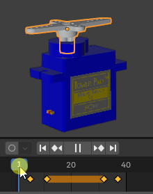
Now, move 5 frames forward to Frame 10. Rotate the servo horn or change the rotation value in the Z-axis field to 180 in the Transform panel. Then click Animate again to insert a keyframe. Now, the servo will rotate from 0 to 180 degrees between Frames 5 and 10. To reverse the movement before the end frame, repeat the same process in reverse. Your servo animation is now ready!
Writing the Arduino Code using blendixserial Library
Download the blendixserial Arduino library from the given link: 🔗Download blendixserial
Then, install it by selecting ‘Add .ZIP Library’ from the ‘Sketch’ > ‘Include Library’ menu.
First, we start by including the necessary libraries: Servo to control the servo motor, and blendixserial to handle communication between Blender and Arduino. In the setup() function, we initialize serial communication and configure the servo motor to be controlled via pin 9. We also set the number of data sets the Arduino expects to receive from Blender, which in this case is 3 (X, Y, and Z coordinates). Inside the loop() function, we continuously check for incoming serial data. When the data is available, we read it byte by byte into a buffer. Once the data is fully received and parsed by the blendix.parseReceivedData() function, we call processCoordinates() to extract the X, Y, and Z coordinates.
The Z-coordinate is then mapped to a value between 0 and 180 (the valid range for the servo). If the new Z-coordinate is different from the last known value, the servo moves to the new position. This ensures that the servo only moves when there’s a significant change in the data, reducing unnecessary movements. Finally, the code continuously listens for data, updates the servo’s position based on the Z-coordinate from Blender, and ensures smooth interaction between the virtual and physical world.
Managing Serial Communication for Blender and Arduino Projects
When integrating Blender animations with physical hardware like a servo motor via an Arduino, you often rely on serial communication to send and receive data. However, many popular Arduino boards (such as the Uno or Nano) come with only one hardware serial port, this same port is used for both programming (via USB) and external communication. This setup can create challenges, especially when you want to maintain live communication with Blender while also having a way to debug your code.
Debugging on a Second Serial Channel
- For Multi-Serial Boards: Boards like the Arduino Mega, Due, Leonardo, or ESP32 have additional hardware serial ports (such as Serial1). In these cases, you can use one of these additional ports for debugging. This keeps the debugging data separate from the Blender communication, allowing you to view messages in the Serial Monitor without interrupting the main data stream.
- For Single-Serial Boards: Since only one hardware serial port is available, you can optionally use the SoftwareSerial library to create a virtual serial port for debugging. Additionally, a USB-to-TTL converter allows you to connect this SoftwareSerial port to your PC. However, because SoftwareSerial may be less reliable or slower than hardware serial, it’s best reserved for essential debugging tasks only.
Single-Port and Multi-Serial Debugging
This code is designed for single-port Arduino boards, such as the Uno or Nano, where the primary Serial port is dedicated to communication with Blender. It utilizes the SoftwareSerial library to create a virtual debugging port on pins 10 and 11, enabling you to receive debugging messages via a USB-to-TTL converter without interfering with the main Serial communication. For multi-serial boards like the Arduino Mega or Due, you can remove the SoftwareSerial code entirely and replace the debugSerial instance with an available hardware serial port (such as Serial1 or Serial2) for more reliable debugging.
blendixserial - Using Blender to Control a Servo Motor
Decide which code you want to use with the Arduino and upload it. I will go with the debugging option. Now, let’s proceed with Blender. If you have already installed the blendixserial addon, press ‘N’ to open the side tool panel, where you will find the blendixserial addon interface. Otherwise, you can download and install it from the following link:
In the Serial Connection panel, connect your Arduino. Then, go to the 3D Object Control panel, where in the Send Mode section, click on the ‘Add New Object to Send’ button. A new selection field will appear for the object, where you can select the servo horn. Click on the Preferences button next to the selection field, where you can choose the property and axis you want to send. In our case, it’s the rotation and the Z-axis. After that, click on the ‘Start Movement’ button and play the animation. Your data will be sent to the Arduino via serial. You will see how your servo moves with the Blender servo animation. That’s cool!

