
Under Voltage Sensing IC MC34064
The under voltage sensing IC, MC34064, is an integrated circuit designed for monitoring voltage levels in systems to prevent them from falling below a critical threshold. It keeps a continuous check on the voltage of a power supply line. When this voltage drops below a specified level, typically determined using an external resistor, the MC34064 identifies this as an under-voltage scenario. In response, it sends a reset signal. This signal can be used to reset microprocessors or other digital circuits within the system.
You can typically find the datasheet for the MC34064 under voltage sensing IC on the manufacturer’s website: onsemi
You can also download the datasheet directly by clicking the button.
Features of the MC34064
Here are the features of the Under Voltage Sensing IC:
Trimmed-In-Package Temperature Compensated Reference: Provides a stable reference voltage across varying temperatures.
Comparator Threshold of 4.6 V at 25°C: Ensures accurate undervoltage detection at standard room temperature.
Comparator Hysteresis Prevents Erratic Reset: Avoids frequent toggling of the reset signal around the threshold voltage.
Reset Output Capable of Sinking in Excess of 10 mA: Supports a strong reset signal by sinking more than 10 milliamps.
Low Standby Current: Minimizes power consumption when the device is inactive.
Understanding the MC34064 Block Diagram
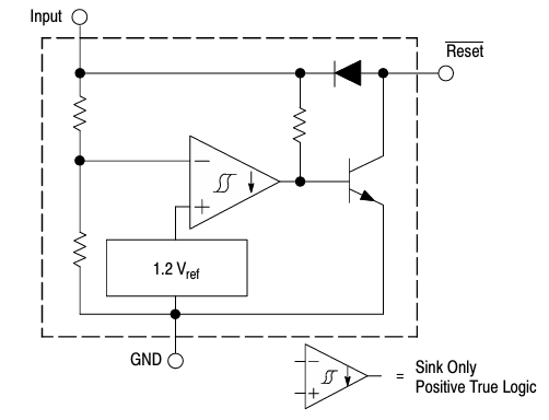
The MC34064 block diagram shows a precise bandgap reference that creates a stable 1.2V, which is essential for accurate voltage detection. This 1.2V is then adjusted to a 4.6V threshold using an internal resistor network, ensuring the comparator has a reliable reference point. The comparator continuously monitors the input voltage against this threshold.
When the input voltage drops below 4.6V, the comparator’s output switches to a low state. This activates the open collector reset output, capable of sinking over 10mA, thereby sending a reset signal. An internal clamp diode helps quickly discharge any delay capacitor, ensuring timely reset operations and preventing erratic behavior.
COMPARATOR Threshold Voltage
High State Output:
This is the input voltage level at which the comparator output switches to a high state (logic 1) as the input voltage increases.
- Typical Value: 4.61 V
Low State Output:
This is the input voltage level at which the comparator output switches to a low state (logic 0) as the input voltage decreases.
- Typical Value: 4.59 V
Hysteresis:
Hysteresis is the difference between the voltage levels at which the output switches states. It helps to prevent rapid switching (chattering) of the output when the input voltage is near the threshold.
- Typical Value: 0.02 V
How It Works
Normal Operation: When the input voltage is above the threshold (4.6V), the comparator output remains inactive, and the reset line stays high due to the pull-up resistor. The system operates normally.
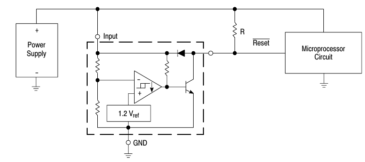
Undervoltage Condition: If the input voltage drops below the threshold, the comparator changes its output state, activating the open collector transistor and pulling the reset line low. This reset signal ensures the microprocessor or system is safely reset, preventing malfunction.
Return to Normal Voltage: When the input voltage rises back above the threshold plus hysteresis, the comparator returns to its original state. The open collector transistor is deactivated, and the reset line is pulled high again by the pull-up resistor.
Under Voltage Sensing IC with Time Delay Reset
Power supplies can experience brief dips and spikes. According to the datasheet, using a capacitor helps filter out minor glitches by maintaining the voltage level for a short period, ensuring that only significant and sustained drops in voltage trigger the reset.
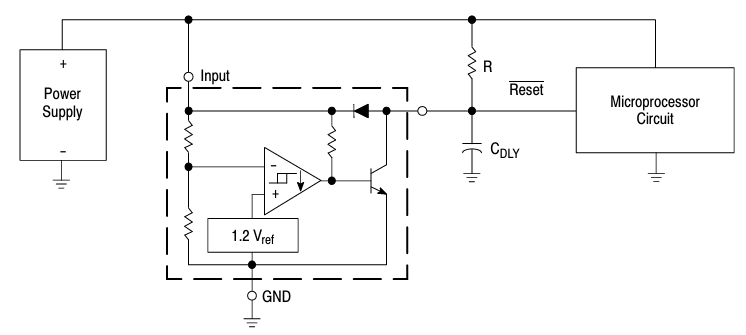
Power-Up Delay:
Voltage Drop Handling:
Under Voltage Sensing Reset with Hysteresis

The diagram describing the comparator’s hysteresis outlines how hysteresis is integrated into the circuit and its impact on the comparator’s performance. Hysteresis is added to stabilize the reset signal. Without it, small fluctuations in the input voltage could cause the comparator to switch states frequently, resulting in false resets of the microprocessor.
Although this change is relatively small, it plays a crucial role in ensuring precise operations. The accuracy of these calculations is maintained within ±10% under specific conditions: when the hysteresis resistor is less than or equal to 150 ohms and when the load resistor is between 1.5 kΩ and 10 kΩ.
Summary
The Under voltage Sensing IC design ensures that your system remains protected from under voltage conditions with precise voltage detection and reliable reset signaling. Its robust features and dependable operation make it an essential component for any sensitive electronic system, from household appliances to automotive and industrial equipment.
In the next post, we’ll use this under voltage sensing IC with Arduino for low voltage scenarios, where we’ll employ it as an External BOD (Brown-Out Detection) device.
Low Voltage Monitoring of Arduino with MC34064


