
In this post, I’ll walk you through what the VRTC (Virtual Real Time Clock) Model is, how it functions, and how you can use it to simulate date and time features in your virtual projects using UART communication.
What is VRTC Model
The VRTC Model is a component that acts like a real time clock chip, using UART for communication. It’s built to run inside Proteus VSM, giving embedded developers a way to simulate timekeeping by interacting with it through a custom UART protocol.
It acts like a peripheral device you can plug into your project and communicate with over serial to:
- Time Reading: Get hour, minute, second.
- Date Reading: Get day, month, year.
- Full timestamp & date retrieval
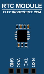
Pin Definitions:
| Pin | Type | Description |
|---|---|---|
V | Digital | Power pin |
G | Digital | Ground pin |
TX | Digital | UART Transmit from VRTC to host |
RX | Digital | UART Receive from host to VRTC |
VRTC UART Command Protocol
Communication with the Real Time Clock Model happens via UART. The protocol is designed to be simple enough for beginner developers and robust enough to simulate real hardware interaction.
VRTC Model Frame Format
Every command frame starts with a fixed header and ends with a CRC checksum for integrity.
[0x55][LEN][CMD][DATA...][CRC]
0x55: Header byte (constant)LEN: Number of bytes in theDATAfieldCMD: Command code (1 byte)DATA: Optional payload (ifLEN > 0)CRC: XOR of all previous bytes
VRTC Model Command Byte Table
| Command Byte | Description | Expected Response Format | Notes |
|---|---|---|---|
0x33 | Get full time | [HH, MM, SS] | Send once per second for clock |
0x34 | Get hours only | [HH] | 24-hour format (0–23) |
0x35 | Get minutes only | [MM] | 0–59 |
0x36 | Get seconds only | [SS] | 0–59 |
0x43 | Get full date | [DD, MM, YY] | Year is two-digit (e.g., 24) |
0x44 | Get day only | [DD] | 1–31 |
0x45 | Get month only | [MM] | 1–12 |
0x46 | Get year only | [YY] | e.g., 24 for 2024 |
Command and Response with Virtual Real Time Clock Model
Send Command to Read Full Time
Let’s say we want to send the “Get Time” command:
| Description | Value |
|---|---|
| HEADER | 0xA5 |
| LEN | 0x00 |
| CMD | 0x33 |
| CRC | 0xA5 ^ 0x00 ^ 0x33 = 0xF6 |
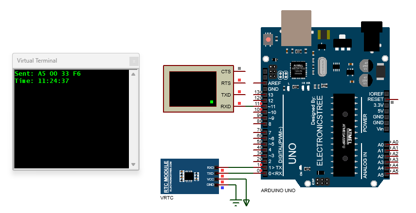
Final Packet (in HEX): A5 00 33 F6
Arduino Code to Send This Command:
void sendVRTCCommand() {
  byte len = 0x00;
  byte crc = HEADER ^ len ^ CMD_GET_TIME;

  Serial.write(HEADER);         // Start byte
  Serial.write(len);            // Data length
  Serial.write(CMD_GET_TIME);   // Command
  Serial.write(crc);            // CRC
  Serial.println("Sent: A5 00 33 F6");
}
Handle the Response from VRTC Model
0x33, you’ll receive a response packet like: A5 03 33 HH MM SS CRC void receiveVRTCResponse() {
if (Serial.available() >= 7) { // Expected: 7 bytes
byte header = Serial.read();
byte len = Serial.read();
byte cmd = Serial.read();
byte h = Serial.read();
byte m = Serial.read();
byte s = Serial.read();
byte crc = Serial.read();
// Verify CRC
byte check = header ^ len ^ cmd ^ h ^ m ^ s;
if (check == crc) {
Serial.print("Time: ");
Serial.print(h); Serial.print(":");
Serial.print(m); Serial.print(":");
Serial.println(s);
} else {
Serial.println("CRC Error!");
}
}
}
If time is 14:25:08, response will be: A5 03 33 0E 19 08 CC
- 0x0E = 14, 0x19 = 25, 0x08 = 08
- CRC = 0xA5 ^ 0x03 ^ 0x33 ^ 0x0E ^ 0x19 ^ 0x08 = 0xCC
Arduino Code
On an Arduino Uno, there’s only one hardware Serial, which is usually used for USB debugging. So if you’re connecting your Virtual Real Time Clock Module to the Arduino, you should:
- Use hardware Serial (
Serial) for VRTC communication. - Use SoftwareSerial to debug via another pair of pins (e.g., D10 and D11).
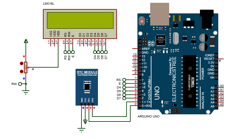
VRTC + LCD Display Example
This Arduino sketch demonstrates how to communicate with a Virtual Real Time Clock (VRTC) module over serial and display the time and date on a 16×2 LCD.
It begins by initializing the LCD and showing a welcome message. Once the setup is complete, the Arduino sends specific commands to the VRTC module over the serial port to request the current time and date. The VRTC responds with a structured data packet that includes the hour, minute, second for time, and day, month, year for the date. The code reads this response, verifies it using a checksum (CRC), and extracts the relevant information. It then updates the LCD to show the current time on the first line and the date on the second line. To keep the display current, the time is refreshed every second and the date is refreshed every ten seconds.
Download Library
Simply click on the button to download the library. You can refer to this post for instructions on how to install the library in Proteus 8. How to Download and install Library in Proteus (electronicstree.com)
ZIP Password : electronicstree.com
If you have any requests for Arduino Module Libraries in Proteus, please leave a comment or message us using the contact form.
Fixing the “External model DLL not found (GLE=0x0000007E)” Error
If you start a simulation and see an error message such as:
or something similar with another DLL name, don’t panic. In most cases the DLL is not really missing. What’s happening is that your system doesn’t have the Visual C++ runtime libraries that the DLL needs in order to run.
The solution is simple. Go to Microsoft’s website and download the latest Visual C++ Redistributable for Visual Studio 2015–2022. You can find it here:
During installation, make sure you install both the x86 (32-bit) and x64 (64-bit) versions. Even on a 64-bit system, some applications depend on the 32-bit runtime, so having both installed avoids errors.
Once the installation is complete, restart your computer. After restarting, try running the simulation again. In most cases the error will disappear and everything will work normally.

