Have you ever been working on a microcontroller project in Proteus and wished you could simulate a camera module without having to buy the actual hardware? Well, I’ve been there too, and that’s exactly what led me to create the ProteusCAM simulation model.
What Does ProteusCAM Actually Do?
The ProteusCAM model is pretty straightforward, it’s a virtual camera that captures a portion of your desktop and sends it over serial communication, just like a real camera module would. When you trigger it, it literally takes a screenshot of a specific area on your screen, converts it to a simple black and white image, and transmits the data via UART.
The coolest part? It even draws a red rectangle around the area it’s capturing, so you can see exactly what the “camera” is looking at. It’s like having a magic window into your desktop that your microcontroller can peer through.
Why I Built It This Way
I wanted something that felt real but was also practical for simulation purposes. Here’s what I decided on:
Screen Capture Instead of Static Images: Sure, I could have just loaded pre-made images, but where’s the fun in that? By capturing the actual screen, you can test your image processing algorithms with real, changing content. Move your mouse, open different windows, display test patterns – your simulated camera sees it all.
Simple 1-bit Format: I kept the image format super simple, just black and white pixels. This makes the data easier to handle in your microcontroller code and keeps transmission times reasonable. Plus, many real embedded vision applications start with simple binary images anyway.
UART Communication: I chose standard serial communication because it’s what most people are comfortable with, and it’s how many real camera modules communicate. No fancy protocols or USB simulation needed.
Smart Parameter Handling: ProteusCAM automatically validates and adjusts configuration parameters. If you set invalid dimensions, it corrects them to valid ranges and logs the changes, preventing simulation errors while keeping you informed.
Features
- Screen Capture: Captures a rectangular area from your desktop
- Visual Feedback: Draws a red rectangle around the capture area
- Serial Communication: Transmits image data via UART
- Configurable Resolution: Adjustable width and height parameters
- 1-bit Format: Converts captured images to monochrome (black/white)
- Trigger-based: Image capture initiated by rising edge on TRIG pin
How It Works
- Trigger Detection: Rising edge on TRIG pin initiates capture
- Screen Capture: Captures specified region from center of screen
- Visual Feedback: Draws red rectangle around capture area
- Image Processing: Converts to 1-bit monochrome format
- Data Transmission: Sends via UART with custom protocol
Pin Configuration
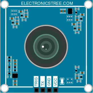
The ProteusCAM model has four pins:
| Pin Name | Type | Direction | Description |
|---|---|---|---|
| TX | Digital Output | Output | Serial data transmission pin |
| TRIG | Digital Input | Input | Trigger pin to initiate image capture |
| VCC | Analog Power | Power | Power supply pin (must be > 4.95V for proper operation) |
| GND | Analog Power | Power | Ground reference pin (must be connected for proper operation) |
ProteusCAM Serial Image Transfer Protocol
ProteusCAM serial communication is implemented with a proper state machine that handles start bits, data bits, and stop bits just like real UART hardware. The protocol I designed is pretty simple:
Physical Layer
- Interface: UART (asynchronous serial)
- Baud Rate:
9600or19200bps (configured via property in the camera model, default 19200) - Data Bits: 8
- Stop Bits: 1
- Idle Line: Logic HIGH
- Protocol: Custom frame format (see below)
Data Layer
The image is sent as a single frame containing one captured bitmap.
[HEADER][LEN_HI][LEN_LO][INDEX][FORMAT][W_HI][W_LO][H_HI][H_LO][IMAGE_DATA][CRC]
- HEADER: A single-byte constant value of 0xA5. It’s used to identify the start of an image frame.
- LEN_HI/LEN_LO: This is a 2-byte field representing the total frame length in a 16-bit, big-endian format. It counts all the bytes that follow it, including the width, height, and image data, but not the header or CRC.
- INDEX: A single-byte field for the frame index, which is currently always 0.
- FORMAT: A single-byte field that specifies the image format. A value of 0 indicates a 1-bit monochrome bitmap.
- W_HI/W_LO: This 2-byte field defines the image width in pixels. It is a 16-bit, big-endian value.
- H_HI/H_LO: This 2-byte field defines the image height in pixels. It is a 16-bit, big-endian value.
- IMAGE_DATA: The actual packed pixel data for the image. Each pixel is represented by a single bit.
- CRC: A single-byte XOR checksum calculated from all bytes in the frame, from the HEADER up to the end of the IMAGE_DATA. This is used for error detection.
ProteusCAM Resolution & Image Format Details
- Resolution Configuration:
- Width: 8 to 240 pixels (must be divisible by 8 for byte alignment)
- Height: 8 to 320
- Image Format:
- Monochrome 1-bit (black & white)
- Packing: 8 pixels per byte (MSB first)
- Thresholding: Pixels with grayscale value greater than 128 are converted to white (
1); others to black (0)
- Frame Size Calculation:
- Maximum frame: 240×320 = 76,800 pixels = 9,600 bytes of image data
- Complete frame: 9,610 bytes including the 10-byte header
- Transmission time: About 5 seconds at 19200 baud
Capture Area Positioning
Default Behavior – Center Capture: ProteusCAM automatically captures from the center of your desktop, not from a corner or random location.
The Math Behind It:
The formula ((screen_width - width) / 2, (screen_height - height) / 2) calculates the top-left corner position of the capture rectangle to center it perfectly.
Example with real numbers:
- Your screen resolution: 1920×1080 pixels
- ProteusCAM configured for: 64×64 pixels
- Calculation:
- X position: (1920 – 64) ÷ 2 = 1856 ÷ 2 = 928 pixels from left
- Y position: (1080 – 64) ÷ 2 = 1016 ÷ 2 = 508 pixels from top
So ProteusCAM would capture a 64×64 square starting at position (928, 508), which centers it perfectly on your screen.
Why Center?
- Predictable: You know exactly where to place test images
- Convenient: Most people naturally put important content in the center
- Visible: Easy to see the red capture rectangle
- Universal: Works on any screen size automatically
Wiring the ProteusCAM Module
Here’s how to connect each of the four pins on the ProteusCAM to your circuit:
- TX: Connect to the microcontroller’s UART RX pin to receive image data.
- TRIG: Connect to a digital output pin on your controller or to a push button/switch. The camera captures an image when this pin goes from LOW to HIGH (rising edge).
- VCC: Connect to a regulated power supply of at least 4.95V.
- GND: Connect to the common ground of your circuit.
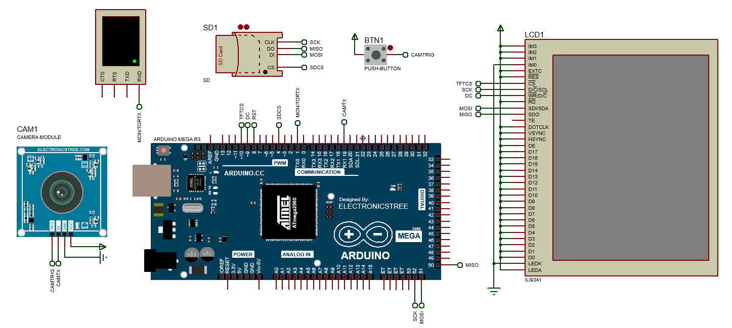
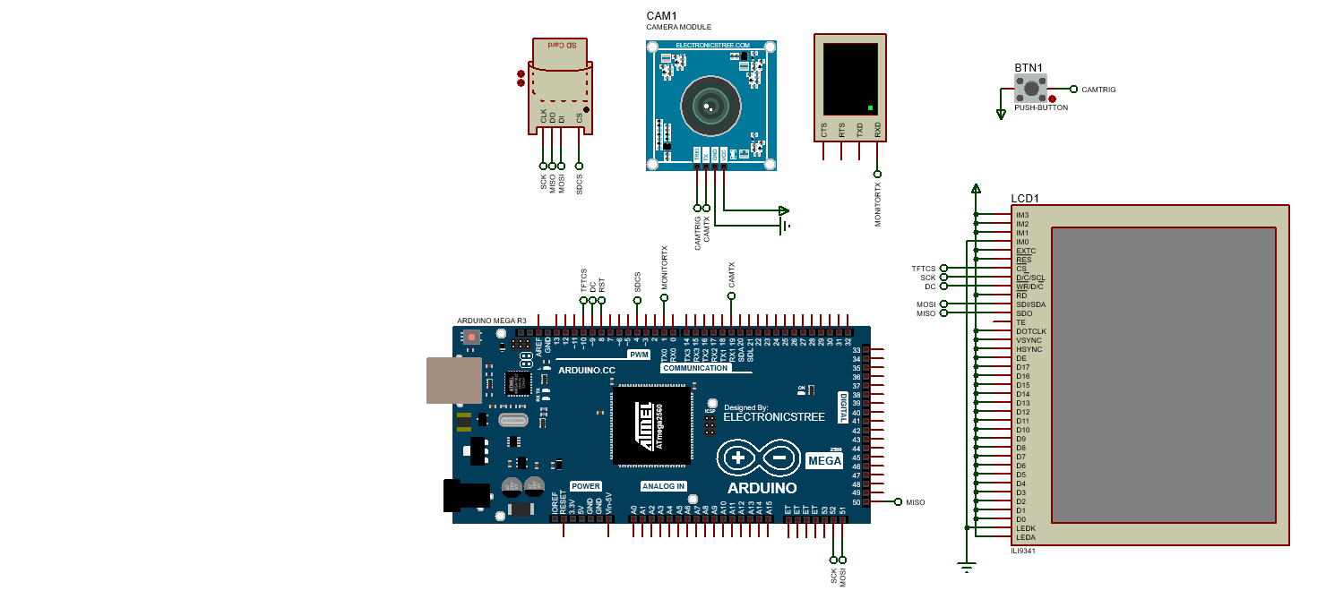
To display the images captured by the ProteusCAM module, you can use a 240×320 SPI TFT display based on the ILI9341 driver. Since the camera outputs monochrome 1-bit image data, you can render it on the TFT by scaling each pixel to a visible block or color-mapping black and white pixels accordingly. The display connects to your microcontroller via the SPI interface using five wires: CS (chip select), DC (data/command), RESET, MOSI (data), and SCK (clock). To store the captured images, connect an SD card module, which also uses SPI but with a separate CS pin.
Arduino Code
This code is designed to capture black-and-white images from ProteusCAM module connected via serial and display them on a small TFT screen, while also saving each image to an SD card. To make this work, we first set up the display, the SD card, and the serial connection with the camera. The camera sends image data starting with a special header byte (0xA5), which tells the Arduino that a new image is coming.
Once we detect this, we read the full image, including some information like its width, height, and pixel data, and write it to a file on the SD card. Each image gets a unique filename so nothing gets overwritten. After saving, we open the file again and draw the image pixel by pixel on the screen, centering it neatly. So overall, this code listens for incoming images, saves them, and shows them, creating a simple but complete system for capturing and viewing images with Arduino.
Download Library
Simply click on the button to download the library. You can refer to this post for instructions on how to install the library in Proteus 8. How to Download and install Library in Proteus (electronicstree.com)
ZIP Password : electronicstree.com
If you have any requests for Arduino Module Libraries in Proteus, please leave a comment or message us using the contact form.
Camera Capture Area Guide — Overlay Tool
This simple tool is designed to help you visually align the screen area that your ProteusCAM is capturing. It acts like a laser guide for your camera’s frame showing exactly what part of your screen will be sent over UART as an image.
Why You Need This Tool
When using ProteusCAM, you’re capturing a small portion of your screen (e.g., 128×64 or 240×320 pixels). But without any visual indication, it’s hard to know what area is being captured.
That’s where this overlay tool comes in. Think of it like a digital viewfinder, it draws a red rectangle right on your screen, centered, matching your camera’s capture dimensions.
What This Tool Does
- Lets you set the width and height of the capture area
- Displays a transparent overlay with a red rectangle in the center of your screen
- Helps you align what content appears inside the virtual camera’s captured frame
- Stays always on top and doesn’t interfere with your mouse
How to Use It
- Run the tool.
- Choose resolution.
In the small control window, set your desired:- Width (e.g., 240)
- Height (e.g., 320)
- These should match the WIDTH and HEIGHT you configure in your ProteusCAM model in Proteus.
- Click “Show Overlay”
A red rectangle will appear on your screen this is exactly what the camera will capture. - Move your windows/content so the important area fits inside the red box. Once aligned, trigger the camera (e.g., via Proteus TRIG pin), and it’ll capture that area.
- Click “Hide Overlay” when you’re done
Download ProteusCAM Tool
ProteusCAM is new and unsigned, some antivirus programs or Windows SmartScreen may display warnings such as:
- Unknown Publisher
- Newly Encountered Program Detected
- Windows protected your PC
This does not mean the file is harmful, it simply means it has not yet been widely recognized by security services.
If you see a warning:
- In Windows SmartScreen, click More info → Run anyway.
- In your antivirus, choose Allow Once or Trust this file.
Why this happens
Even safe apps can be flagged when they are:
- Newly released (no download history yet)
- Unsigned (no paid code-signing certificate)
- Distributed via direct download or email attachment
Open-Source & DIY Build Option
ProteusCAM is completely open-source, you are welcome to:
- Download the full Python source code.
- Run it directly without any EXE.
- Build your own EXE with PyInstaller.
Video Guide
Fixing the “External model DLL not found (GLE=0x0000007E)” Error
If you start a simulation and see an error message such as:
or something similar with another DLL name, don’t panic. In most cases the DLL is not really missing. What’s happening is that your system doesn’t have the Visual C++ runtime libraries that the DLL needs in order to run.
The solution is simple. Go to Microsoft’s website and download the latest Visual C++ Redistributable for Visual Studio 2015–2022. You can find it here:
During installation, make sure you install both the x86 (32-bit) and x64 (64-bit) versions. Even on a 64-bit system, some applications depend on the 32-bit runtime, so having both installed avoids errors.
Once the installation is complete, restart your computer. After restarting, try running the simulation again. In most cases the error will disappear and everything will work normally.

Hello Usman, thank you for creating this library. I am trying to use the ProteusCAM model, but the simulation fails with the error: “External model DLL ‘PROTEUSCAM.DLL’ not found. GLE=0x0000007E”.
I used the Dependencies tool to analyze the DLL, and it shows that it is a Debug build that is missing the debug runtimes (MSVCP140D.dll, VCRUNTIME140D.dll).
Could you please compile and upload a Release build of the library? I believe this will fix the issue for everyone. Thank you!
Hi, it looks like you’re facing a common Proteus issue 🙂
The error “External model DLL PROTEUSCAM.DLL not found. GLE=0x0000007E” usually means Proteus can’t locate the required file. Please try this:
Locate the PROTEUSCAM.dll file in the MODEL folder of the library.
Copy it and paste it into your main Proteus MODEL folder inside the installation directory.
Restart Proteus.
If the error still appears, you can also paste the PROTEUSCAM.dll into the same folder where your project file is saved.
Just to clarify, every model that has a DLL file is tested by me on at least two different PCs before uploading, so I’m confident it should work. But if the problem continues, let me know and I’ll run further testing 👍
Hi Usman,
Thank you so much for the quick reply and for your willingness to help!
I followed your suggestion and copied the PROTEUSCAM.dll file into the same folder where my project file is saved. Unfortunately, I am still getting the exact same error: External model DLL “PROTEUSCAM.DLL” not found. GLE=0x0000007E.
To help with the further testing you mentioned, I did a much deeper investigation using a tool called Dependencies. It has revealed the specific reason the DLL is failing to load on user machines, and it explains why it would work on your test PCs but not for others.
The PROTEUSCAM.DLL you have provided seems to be a Debug build, not a Release build.
The analysis shows it requires specific debug-only files (MSVCP140D.dll, VCRUNTIME140D.dll, and ucrtbased.dll) that are only present on a computer with the full Visual Studio development environment installed. This is most likely why it works for you, but it fails for regular users who only have the standard Microsoft C++ Redistributables. The error even persists on a completely fresh installation of Windows.
I would be really grateful if you could recompile the project and provide a Release build of the DLL. This will link it against the standard libraries and should work perfectly for all users.
If creating a Release build isn’t possible for some reason, could you let me know which specific version of Visual Studio and the Windows SDK you used to compile it? I could then try to install that exact developer environment as a last resort.
Thank you again for your help and for creating this great tool. I’m looking forward to getting it running!
Hi Anesu,
Thank you for your detailed investigation and clear explanation, that’s really helpful. At the moment, I don’t have access to my development PC since I’m away on vacation. I’ll be back in the office on 28th/29th August, and at that time I’ll provide you with a proper Release build of the DLL.
I truly appreciate your patience, and I’ll make sure to share the Release version as soon as I’m back. Even if I forget, please feel free to remind me again via a comment here or through the contact form.
That’s fantastic news, and thank you so much for the confirmation! I completely understand and will happily wait for the Release build after the 29th.
I really appreciate you taking the time to respond while on vacation. Enjoy the rest of your time off!
Hi Anesu, the release version is out. You can test the model and share your feedback.