I’ve been tinkering in Proteus again, and this time I tried to build a pressure transmitter model that works on the 4–20 mA current loop. Proteus doesn’t include any ready-made pressure transmitters, so I thought it would be fun (and useful) to create one myself. I loosely based it on the WIKA A10, which is a common industrial pressure transmitter. My version isn’t a perfect copy of the real hardware, but it’s close enough to let you experiment with current loops and see how they behave in simulation.
Why bother with 4~20 mA anyway?
Most people start with sensors that spit out voltage, but industry has stuck with current loops for decades, and for good reason.
- Current doesn’t fade over long cables the way voltage does.
- It’s way less sensitive to electrical noise.
- 4 mA = 0% of scale, 20 mA = 100% of scale. Simple.
- If the wire breaks, the loop drops to 0 mA, which is a neat built-in error check.
Proteus Pressure Transimtter Model
The WIKA A10 series of 4–20 mA pressure transmitters are designed to fit a wide range of industrial applications such as machine building, machine tools, measurement and control systems, hydraulics, pneumatics, pumps, and compressors. The A10 is known for its reliability, quality, and ease of installation and setup. If you’re interested, you can check them out on WIKA’s website.
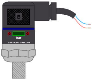
This simplified version doesn’t capture every internal detail of the real device but behaves close enough for simulation and Arduino testing.
Proteus model specs:
- Model: A-10
- Measuring range: 0–100 bar
- Output signal: 4–20 mA
- Interface: 2-wire
- Power supply: 12–30 V DC
Converting Current to Voltage
Arduinos (and most microcontrollers) measure voltage, not current. To bridge that gap, we use a load resistor.
A 250 Ω resistor is the standard choice:
- At 4 mA, the voltage is 4 mA × 250 Ω = 1 V
- At 20 mA, the voltage is 20 mA × 250 Ω = 5 V
So the current loop signal turns into a neat 1–5 V voltage that fits perfectly into Arduino’s 0–5 V ADC input range.
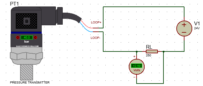
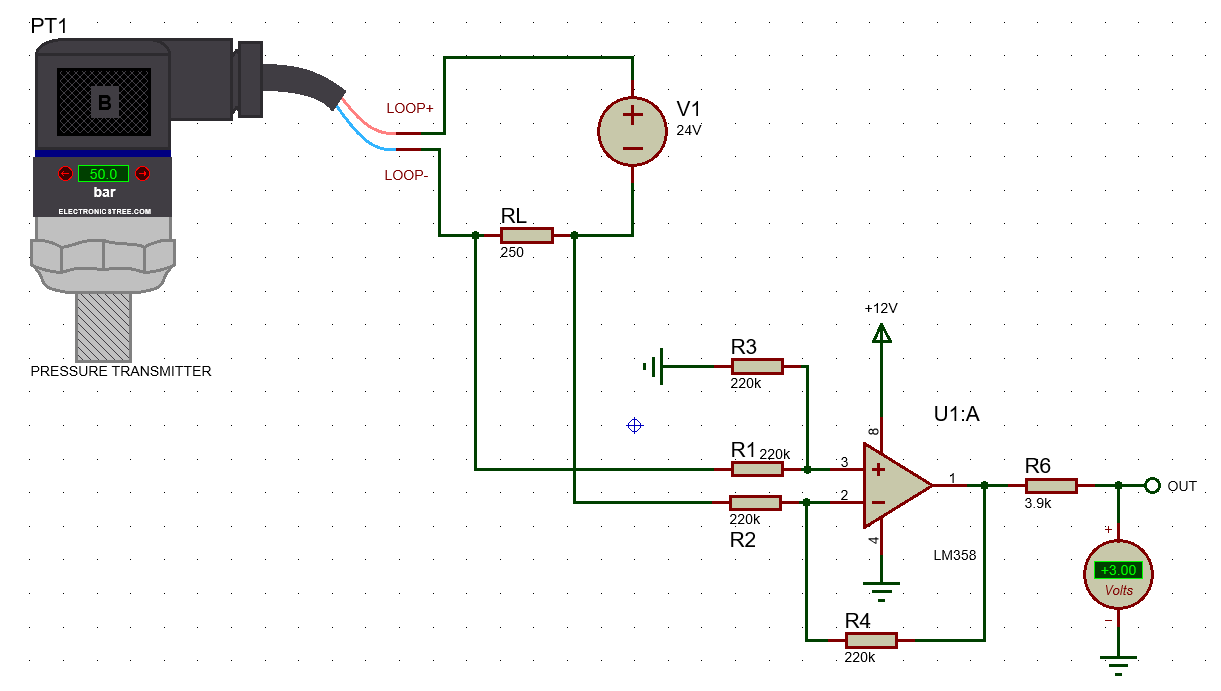
Grounding Matters
One important thing to note: don’t ground the circuit. For example, if you tie the negative side of the 24 V supply or the 0 V end of the resistor to earth ground, the transmitter won’t work properly. This is because the 24 V loop supply and the transmitter’s internal op-amp are designed to operate in a floating configuration, not tied to a common ground.
When you can’t tie the loop ground to your circuit ground, place a 250 Ω resistor in the loop and sense the voltage across it with an amplifier. Power the amplifier from a small isolated supply, and its output gives a clean, ground-referenced 1–5 V signal that any microcontroller can read safely.
Interfacing Pressure Transmitter with Arduino
Once the loop was sorted out, the Arduino code was the easy part: just read the voltage and map it to pressure.
At 1 V it prints 0 bar, at 5 V it prints 100 bar, and everything in between scales linearly.
Download Library
Simply click on the button to download the library. You can refer to this post for instructions on how to install the library in Proteus 8 and Proteus 9.
ZIP Password : electronicstree.com
We’re always looking to expand our library collection based on what our community needs. If you’re looking for a specific Arduino module, sensor, or component that we don’t currently offer, we’d love to hear from you!
Reach out to us at help@electronicstree.com with your requests. We prioritize new library development based on community demand, so your suggestion could be our next addition.


Your comment is awaiting moderation.
ISIS Release 8.17.02 (Build 37159) (C) Labcenter Electronics 1990- 2024.
Netlist compilation completed OK.
Cannot find model file ‘WIKAPT420.MDF’.
Pin ‘LOOP-‘ is not modelled. [PT1]
Pin ‘LOOP+’ is not modelled. [PT1]
Simulation FAILED due to netlist linker error(s).
Hello!
How can I solve this?
Place the WIKAPT420.MDF file in the Proteus Models Folder.