Simulating a physiological signal like a pulse waveform is very different from generating a simple periodic signal. A real pulse is asymmetric, variable, rate-dependent, and noisy by nature. Pulse Sensor model was designed to capture those characteristics while remaining stable, efficient, and easy to integrate into mixed-signal simulations. This post explains the features and internal working of the pulse sensor simulation model.
Pulse Sensor Simulation Model
The pulse sensor model emulates an optical photoplethysmography (PPG) signal, similar to what is produced by common pulse sensors used with microcontrollers and wearable devices.
The output is a continuous analog waveform that:
- Tracks heart rate
- Includes natural beat-to-beat variation
- Produces a realistic systolic peak and dicrotic notch
- Scales correctly with supply voltage
- Can be controlled dynamically
Key Features
Realistic Pulse Waveform Shape: Rather than using a square or sine wave, the pulse shape is synthesized using smooth, rounded curves that resemble a real arterial pressure waveform.
Heart Rate Variability: Real heartbeats are never perfectly periodic. To reflect this, the model introduces small, controlled beat-to-beat timing variations.
Dynamic BPM Control: One of the most powerful features of this model is the real-time BPM control. Instead of relying only on a fixed property value, the heart rate can be driven dynamically using an external Arrow buttons.
Mode-Based Presets: The model supports predefined operating modes that instantly configure it for different physiological conditions. These modes provide quick setup while still allowing fine-grained adjustment through parameters.
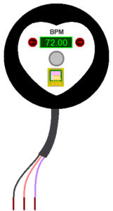
Sensor Pins
The sensor exposes four main connections:
- VCC – Power supply
- GND – Ground
- SIG – Analog pulse output
The sensor behaves like an active device powered by VCC and GND, producing its signal on SIG.
Pulse Sensor Modes
This pulse sensor simulation model is designed to be easy to use even if you are not familiar with physiology or medical terms. To help with this, the model offers two ways to control the pulse output:
- Simple preset modes (quick and easy)
- Manual tuning options (full control)
You can choose either approach or combine both.
Available Modes
- Normal – Balanced, clean pulse for general testing
- Fast – Faster-looking pulses for speed stress testing
- Weak – Very small pulses for sensitivity testing
- Bumpy – Strong secondary bump for shape analysis
- Irregular – Uneven pulse timing for robustness testing
Modes in this pulse simulation model are simple presets that define how the pulse looks and behaves, such as its shape, strength, smoothness, and natural variability. They are meant to help users get a realistic signal quickly without manually adjusting many parameters. Choosing a mode does not fix or lock the pulse speed. The pulse rate (BPM) is always taken from the BPM buttons ( external arrow markers), even when a preset mode is selected. This means the BPM can be changed dynamically during simulation and the pulse will immediately speed up or slow down.
All modes can also be manually customized, any user-defined settings override the preset values, allowing full control over the pulse output while still benefiting from the convenience of presets.
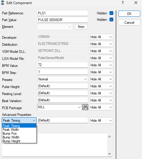
Manual Control Is Always Available
Presets are optional. The sensor allows manual control of:
- Pulse Height
- Resting Level
- Beat Variation
- Peak Timing
- Peak Width
- Bump Pos
- Bump Width
- Bump Height
If manual values are provided, they override preset values automatically.
Nothing is locked.
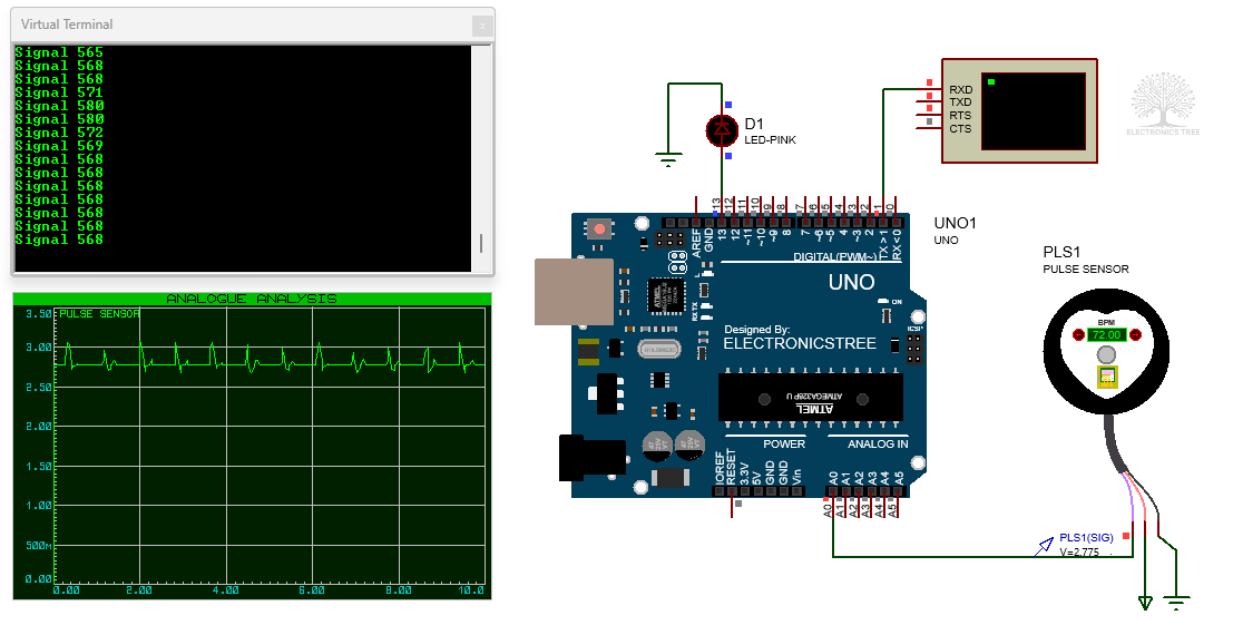
Using the Pulse Sensor with Arduino Uno + PulseSensor Playground Library
The PulseSensor library includes a set of built-in example sketches that are very helpful when you’re first getting started. They show how the sensor behaves and demonstrate how the library handles pulse detection, which makes it easier to understand what’s going on behind the scenes.
You can find these examples in the Arduino IDE by going to File → Examples → PulseSensor Playground.
There are several sketches available, and you’re welcome to explore them later. For your first test, however, it’s best to start with the GettingStartedProject, as it provides a simple and clear introduction to using the sensor.
/*  PulseSensor Starter Project and Signal Tester
 *  The Best Way to Get Started  With, or See the Raw Signal of, your PulseSensor.com™ & Arduino.
 *
 *  Here is a link to the tutorial
 *  https://pulsesensor.com/pages/code-and-guide
 *
 *  WATCH ME (Tutorial Video):
 *  https://www.youtube.com/watch?v=RbB8NSRa5X4
 *
 *
-------------------------------------------------------------
1) This shows a live human Heartbeat Pulse.
2) Live visualization in Arduino's Cool "Serial Plotter".
3) Blink an LED on each Heartbeat.
4) This is the direct Pulse Sensor's Signal.
5) A great first-step in troubleshooting your circuit and connections.
6) "Human-readable" code that is newbie friendly."

*/


//  Variables
int PulseSensorPurplePin = 0;  // Pulse Sensor PURPLE WIRE connected to ANALOG PIN 0
int LED = LED_BUILTIN;         //  The on-board Arduion LED


int Signal;           // holds the incoming raw data. Signal value can range from 0-1024
int Threshold = 580;  // Determine which Signal to "count as a beat", and which to ingore.


// The SetUp Function:
void setup() {
  pinMode(LED, OUTPUT);  // pin that will blink to your heartbeat!
  Serial.begin(57600);  // Set's up Serial Communication at certain speed.
}

// The Main Loop Function
void loop() {

  Signal = analogRead(PulseSensorPurplePin);  // Read the PulseSensor's value.
  // Assign this value to the "Signal" variable.

// Send "reading " followed by the Signal value to Serial Plotter.
  Serial.println("Signal " + String(Signal));

  if (Signal > Threshold) {  // If the signal is above "550", then "turn-on" Arduino's on-Board LED.
    digitalWrite(LED, HIGH);
  } else {
    digitalWrite(LED, LOW);  //  Else, the sigal must be below "550", so "turn-off" this LED.
  }

  delay(20);
}
🪧 Make sure to change the baud rate from 115200 to 57600 in the sketch, because the Proteus terminal supports a maximum baud rate of 57600 only.
Typical Use Cases
This pulse sensor model is well-suited for:
- Testing heart rate detection algorithms
- Validating ADC scaling and filtering
- Developing wearable firmware without hardware
- Simulating physiological responses to control signals
- Educational demonstrations of bio signal processing
Download Library
Simply click on the button to download the library. You can refer to this post for instructions on how to install the library in Proteus 8. How to Download and install Library in Proteus (electronicstree.com)
ZIP Password : electronicstree.com
We’re always looking to expand our library collection based on what our community needs. If you’re looking for a specific Arduino module, sensor, or component that we don’t currently offer, we’d love to hear from you!
Reach out to us at help@electronicstree.com with your requests. We prioritize new library development based on community demand, so your suggestion could be our next addition.
Fixing the “External model DLL not found (GLE=0x0000007E)” Error
If you start a simulation and see an error message such as:
or something similar with another DLL name, don’t panic. In most cases the DLL is not really missing. What’s happening is that your system doesn’t have the Visual C++ runtime libraries that the DLL needs in order to run.
The solution is simple. Go to Microsoft’s website and download the latest Visual C++ Redistributable for Visual Studio 2015–2022. You can find it here:
During installation, make sure you install both the x86 (32-bit) and x64 (64-bit) versions. Even on a 64-bit system, some applications depend on the 32-bit runtime, so having both installed avoids errors.
Once the installation is complete, restart your computer. After restarting, try running the simulation again. In most cases the error will disappear and everything will work normally.