
This ambient light sensor uses the Modbus-RTU protocol to communicate over a standard TX/RX serial interface. It gives you real-time illumination readings in Lux by processing data from user input. You can also configure various settings like how often it takes readings, calibration options, and compensation values.
I have designed this model to closely mimic how a DFRobot Ambient Light Sensor based on Modbus works. This model is part of an ongoing series. Previously, I developed simulation models for the Digital Shake Sensor, Water Pressure Sensor and the Liquid Level Sensor, feel free to explore those as well if you haven’t already. As noted earlier, these simulations are inspired by various analog and digital sensor modules featured on the DFRobot website.
Pin Configuration
The ambient light sensor model has four pins:
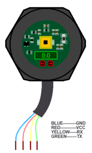
| Pin Name | COLOR | Direction | Description |
|---|---|---|---|
| TX | Digital Output | Output | Modbus RTU transmit line |
| RX | Digital Input | Input | Modbus RTU receive line |
| VCC | Analog Power | Power | Power supply pin |
| GND | Analog Power | Power | Ground reference pin |
Ambient Light Sensor Features
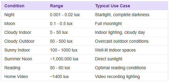
- Measurement Range: Based on selected light condition presets, scaled to realistic lux levels
- Output Resolution: 0.001 lux (lux × 1000 integer representation)
- Protocol: Modbus RTU
- Slave Address: Configurable via device property (default: 1)
- Baud Rates: 1200, 2400, 4800, 9600, 19200 bps
- Parity Modes: None, Odd, Even
- Register Access: Read-only, Read/Write, and Command registers
- Calibration: Enable/disable with adjustable compensation factor
Light Condition Presets
How Modbus Frames Work
Here’s what each Modbus frame contains:
- Address: 1 byte, this tells the sensor which device you’re talking to (uses the default address from properties)
- Function Code:
0x03– Read Holding Registers (for getting data)0x06– Write Single Register (for changing settings)
- Data Area: Variable length (16-bit values use big-endian format)
- CRC: 2 bytes for error checking (low byte comes first)
Important: You need to wait at least 4 character times between frames, this gives the sensor time to process your request.
Ambient Light Sensor Register Map
Ambient light sensor model implements a total of 10 Modbus holding registers.
Out of these, 2 registers are read-only for illumination data, 4 registers are read-only for device information, 3 registers are read-write for operational settings, and 2 registers are write-only for reset commands.
- Read-only (6 total): 0x0002, 0x0003 (lux data), 0x0064, 0x0065, 0x0066, 0x0067 (device info).
- Read/Write (3 total): 0x0046 (acquisition rate), 0x0047 (calibration enable), 0x0048 (calibration compensation).
- Write-only (2 total): 0x00E0 (soft reset), 0x00F0 (factory reset).
| Address (Hex) | Address (Dec) | Register Name | Access | Description |
|---|---|---|---|---|
| 0x0002 | 2 | Illumination High Word | R | High 16 bits of scaled lux (lux × 1000) |
| 0x0003 | 3 | Illumination Low Word | R | Low 16 bits of scaled lux (lux × 1000) |
| 0x0046 | 70 | Acquisition Rate | R/W | Sampling rate: 1 = 1s, 20 = 50ms (linear scale) |
| 0x0047 | 71 | Calibration Enable | R/W | 0 = Disabled, 1 = Enabled |
| 0x0048 | 72 | Calibration Compensation | R/W | Compensation factor ×100 (e.g., 140 = 1.40×) |
| 0x0064 | 100 | Device Address | R | Modbus slave address |
| 0x0065 | 101 | Baud Rate Selection | R | 0=1200, 1=2400, 2=4800, 3=9600, 4=19200 |
| 0x0066 | 102 | Parity Mode | R | 0=None, 1=Odd, 2=Even |
| 0x0067 | 103 | Firmware Version | R | Version number (e.g., 0x0100) |
| 0x00E0 | 224 | Soft Reset | W | Write any value to reset device |
| 0x00F0 | 240 | Factory Reset | W | Write any value to reset all settings |
Measurement Process
Data Acquisition
- The sensor continuously samples the values set by the user from the increment and decrement arrows at a rate determined by the Acquisition Rate register (0x0046).
- The sampled raw value is scaled into lux based on the currently configured light condition profile (set via simulation properties).
- The scaled value is multiplied by 1000 and split into two 16-bit registers for Modbus transmission:
- High Word →
0x0002 - Low Word →
0x0003
- High Word →
Calibration
When Calibration Enable (0x0047) is set to 1:
- The sensor applies a calibration compensation factor from register
0x0048to the measured lux value. - This factor is entered as an integer representing ×100 of the actual multiplier.
- Example:
140→ 1.40× multiplier
- Example:
- Calibration is applied after scaling the raw input value.
- Disabling calibration (
0x0047 = 0) stops applying the factor but retains the last set compensation value.
Acquisition Rate Control
- Register
0x0046sets the lux data ( set by the user ) sampling interval. - Values range from 1 to 20:
- 1 = 1 s
- 20 = 50 ms
- Intermediate values scale linearly.
Differences from DFRobot Ambient Light Sensor
Ambient Light Sensor model follows DFrobot’s Modbus-RTU sensor structure but with some differences.
The registers for device address (0x0064), baud rate (0x0065), and parity (0x0066) are implemented as read-only, while the DFrobot version allows writing to change them. In DFrobot’s hardware, such changes require a power cycle; in our model they are fixed from simulation properties and do not require a restart.
Baud rate support is limited to 19200 bps maximum, while DFrobot supports up to 57600 bps.
The Modbus Write Multiple Registers (function 0x10) used by DFrobot for bulk updates is not implemented here, only Write Single Register (0x06) is supported.
Reading Lux Values from the Ambient Light Sensor
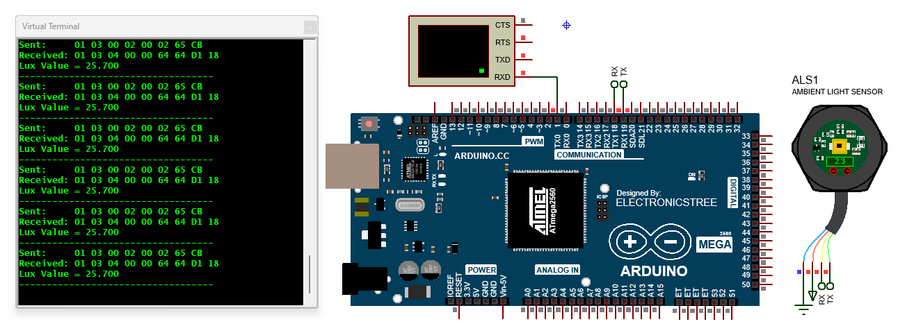
To get a light reading from the MBLS sensor, the Arduino creates a simple request message. This message tells the sensor which device should respond, what data it wants (the lux reading), and where to find that data in the sensor’s registers. The Arduino adds a CRC checksum to catch any transmission errors, then sends the request over the serial connection.
When the sensor responds, the Arduino first checks the CRC to make sure the data came through correctly. Once verified, it combines the two register values into a single reading and converts from milli-lux to lux for easier reading. The final light intensity value then appears on the Serial Monitor, giving you real-time brightness measurements.
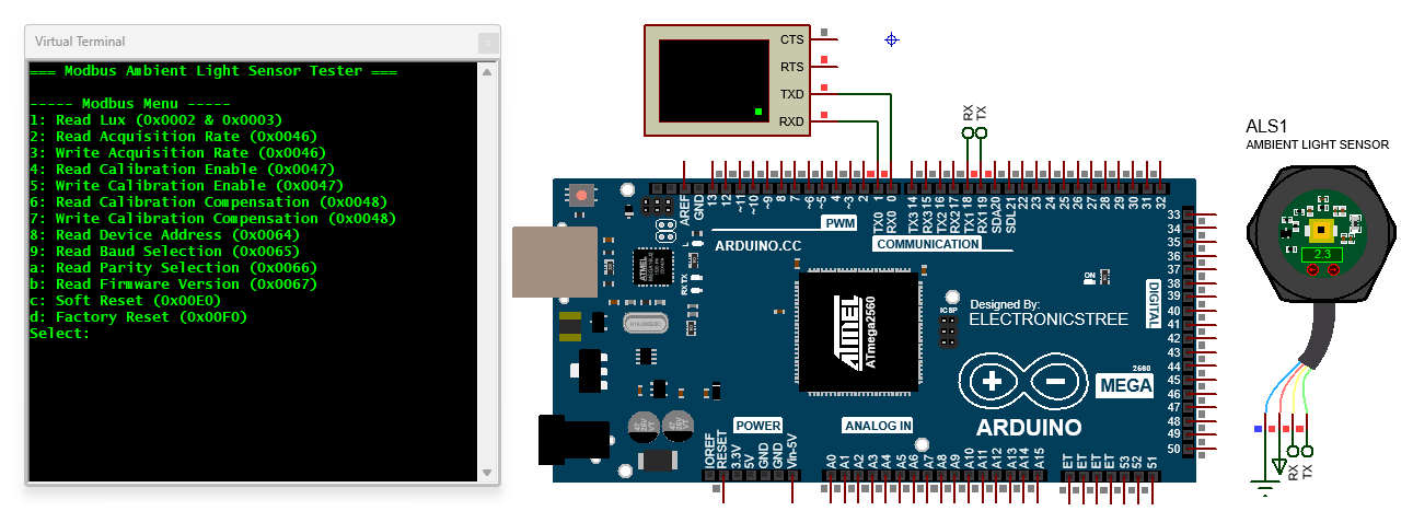
Arduino Modbus RTU Tester for Ambient Light Sensor
This sketch turns your Arduino Mega into a Modbus RTU master that can fully communicate with the Light Sensor model inside Proteus. When you open the Serial Monitor, the Arduino displays a clear menu with different options such as reading the light value, checking or changing the acquisition rate, enabling or disabling calibration, and even sending reset commands to the sensor. You simply press a number or letter on your keyboard, and the Arduino builds the correct Modbus command frame in the background.
This menu-based approach makes the sketch very flexible. You can test individual registers one by one, adjust settings like acquisition rate or calibration, and even perform special operations such as soft reset or factory reset, all without having to rewrite any code. The Arduino acts as a “tester tool,” giving you full control of the sensor through a simple keyboard menu.
Download Library
Simply click on the button to download the library. You can refer to this post for instructions on how to install the library in Proteus 8. How to Download and install Library in Proteus (electronicstree.com)
ZIP Password : electronicstree.com
We’re always looking to expand our library collection based on what our community needs. If you’re looking for a specific Arduino module, sensor, or component that we don’t currently offer, we’d love to hear from you!
Reach out to us at help@electronicstree.com with your requests. We prioritize new library development based on community demand, so your suggestion could be our next addition.
Fixing the “External model DLL not found (GLE=0x0000007E)” Error
If you start a simulation and see an error message such as:
or something similar with another DLL name, don’t panic. In most cases the DLL is not really missing. What’s happening is that your system doesn’t have the Visual C++ runtime libraries that the DLL needs in order to run.
The solution is simple. Go to Microsoft’s website and download the latest Visual C++ Redistributable for Visual Studio 2015–2022. You can find it here:
During installation, make sure you install both the x86 (32-bit) and x64 (64-bit) versions. Even on a 64-bit system, some applications depend on the 32-bit runtime, so having both installed avoids errors.
Once the installation is complete, restart your computer. After restarting, try running the simulation again. In most cases the error will disappear and everything will work normally.

