Are you looking for a Modbus RTU sensor to simulate in Proteus 8? Look no further! This blog post will introduce you to the Modbus RTU Sensor Library for Proteus. You can easily simulate your industrial automation projects using this library. If you don’t know about Modbus or if you’re a beginner, you can first refer to this post, which explains Modbus in the easiest way possible.
What Is The Modbus Protocol And How Does It Work? An Easy Explanation For Beginners
Modbus RTU Sensor Library for Proteus
With our Modbus RTU Sensor Library, you can simulate a temperature and humidity sensor within Proteus 8, a leading simulation software for electronic design and testing. This simulation capability is invaluable for prototyping and testing your Modbus RTU communication without physical sensors. Simply add our Modbus RTU Sensor Library to your Proteus 8 project to start simulating temperature and humidity data.
The library model provides realistic sensor data, mimicking actual sensor behavior for accurate testing and development. You can adjust the simulation mode, such as temperature and humidity settings, either automatically or manually, to suit your specific needs.
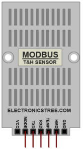
Modbus RTU devices typically use an RS-485 interface for communication. This interface allows for bidirectional communication using differential signaling, which is well-suited for industrial environments due to its robustness against noise and long-distance capabilities. RS-485 uses two wires for communication: one for transmitting data (TX) and one for receiving data (RX). Additionally, RS-485 supports multi-drop configurations, allowing multiple devices to communicate on the same bus using unique addresses.
This Modbus model is based on the UART interface, so you can communicate Modbus RTU over UART with another UART device (such as Arduino or other microcontrollers) without using additional physical layers like RS-485 or RS-232. However, the drawback is that you can only use this model for point-to-point communication and can’t achieve the multidrop configuration like RS-485.
How to use Modbus RTU Sensor
Installation:
First, download the Modbus RTU sensor library from the link provided at the end of the post. After downloading, extract the library folder and you will find the LIB folder inside it.
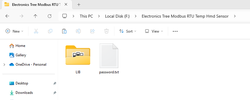
This folder contains two files: one is the Modbus RTU sensor library file and the other is its hex firmware file.

Copy both these files to the Proteus library folder. After that, open the Proteus folder, and if it’s already open, restart it. Now, search for Modbus in the component search bar and place it on the schematic sheet.

Open the properties window of the Modbus sensor, where you will find the option for MODBUS FIRMWARE. Here, you need to select the hex firmware file, and your Modbus sensor for simulation is ready to use.
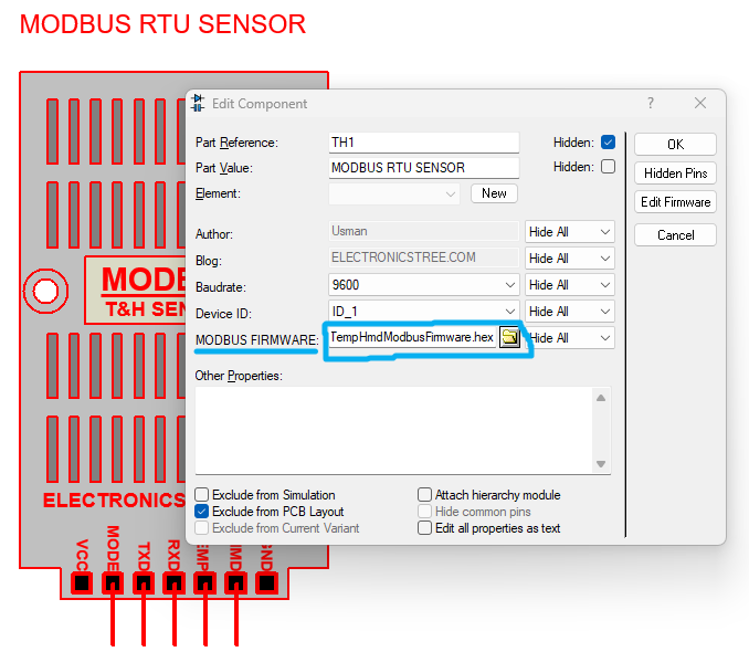
Overview of Modbus RTU Sensor:
This sensor model has a total of five pins. The VCC and GND pins are not required because Proteus can power it by default. By setting the mode pin to high, you can select manual mode for the sensor. In manual mode, you can use the TEMP and HMD pins to manually update the sensor values. If you set this pin to low (or leave it open), the sensor will operate automatically and update its values by itself, which you can then read. The RX and TX pins are available for UART communication.
Communication Parameters of Modbus RTU Sensor:
- Baud Rate: 9600
- Parity: None.
- Data Bits: 8.
- Stop Bits: 1.
- Modbus Protocol: Modbus RTU (binary format).
- Supported Modbus Commands:
- Read Holding Registers (Function Code 0x03).
Modbus Details:
- Modbus Slave Address:
0x01 - Modbus Function Codes Supported:
- Read Holding Registers (Function Code 0x03).
- Holding Registers:
- Start Address:
40001(Modbus address convention). - End Address:
40010(Modbus address convention). - Total Registers: 10 (16-bit each).
- Register Values:
- Temperature data (16-bit).
- Humidity Data value (16-bit).
- Remaining registers are free for testing.
- Start Address:
Operational Modes:
- Auto Mode: Increments temperature and Humidity value automatically based on a predefined increment.
- Manual Mode: Reads analog values (TEMP and HMD) to set temperature and Humidity.
You can test this sensor without a microcontroller using any Modbus master device. Here’s how you can do it.

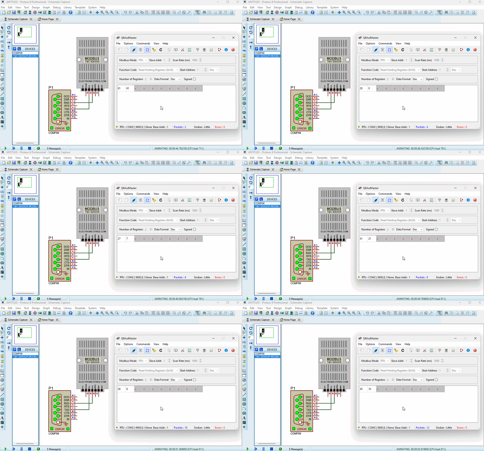
In Proteus, connect the sensor to the serial port and configure the serial port settings as shown in the image.

To select the serial port, you need to create a virtual COM port using any application, and then choose the corresponding linked COM port in the field. In my case, I used Virtual Serial Port Tools software to create COM1.

Now, choose any Modbus master application for testing the sensor. You can find many Modbus master apps on the internet for free, so choose the one you prefer. I’m using the QModMaster application to read this sensor. For the Modbus communication mode, select RTU. In the slave address, put 1 because the Modbus RTU sensor I designed has a slave ID of 1. After that, select function code 3 to read the holding register of the sensor.
Then, choose the start address of the holding register; in this case, select 1. Next, select how many registers you want to read; in this field, select 2. In the serial communication settings, select COM port 2, which is the second side-linked port. After the settings, you can start reading the Modbus sensor. Here are the simulation results.
In the next post, we will interface the Modbus sensor with Arduino in Proteus. Stay connected to our site for updates.
Download Library
Simply click on the button to download the library. You can refer to this post for instructions on how to install the library in Proteus 8. How to Download and install Library in Proteus (electronicstree.com)
ZIP Password : electronicstree.com
If you have any requests for Arduino Module Libraries in Proteus, please leave a comment or message us using the contact form.


HEllo!
pls the password is not working. help me out
I have fixed the link👍
thanks sir,god bless you
password wrong
I have tested the ZIP file again, and the password is functioning correctly.
Password: electronicstree.com