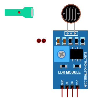
An LDR module is a small circuit board that includes a Light Dependent Resistor (LDR) along with other components, like resistors and a comparator or operational amplifier (op-amp). These components work together to make it easy for microcontrollers, like an Arduino or Raspberry Pi, to detect and respond to changes in light levels.
In practical use, LDR modules are handy for projects like automatic night lights, alarms that trigger in response to changing light, or even smart devices that adjust based on light conditions. The module makes it straightforward to add light-sensing capabilities to electronics projects without needing to handle the circuit details yourself.
Proteus LDR Module
This is another model from my Proteus library development series. It’s designed to work just like a real LDR hardware module, making it easy to simulate and experiment with light-dependent circuits in Proteus. The module includes animations and graphics that create a more interactive and visually engaging simulation, which is especially useful for testing and understanding how LDR modules function in different lighting conditions

With this LDR module, you can access both digital and analog outputs. The analog output provides a continuous reading of light levels, reflecting the exact amount of light the sensor detects. On the other hand, the digital output is set up to deliver a simple high or low signal depending on a light threshold, making it useful for applications where you want a clear “on” or “off” response to light changes.
In the model’s properties menu, you can adjust both the light threshold for the digital output and the LDR resistance itself, giving you more control over how the module responds in your simulation. This flexibility makes it ideal for creating responsive designs that depend on light sensitivity.
How to Use it with Arduino
Wiring the Module to Arduino:
- VCC (Sensor Pin) → Connect to the 5V
- GND (Sensor Pin) → Connect to the GND
- A0 (Analog Output Pin of the Sensor) → A0 (Analog Input Pin of Arduino)
- D0 (Digital Output Pin of the Sensor) → (Connect to any Arduino digital input pin)
Arduino Code
Code Explanation
Alright, so this code is set up to work with an LDR module. When the code first runs, it sets up a few things: it turns on serial communication so we can see messages on the Serial Monitor, and it sets up the built-in LED on the Arduino as an output.
It reads the digital pin connected to the module to see if the light is above or below the threshold. If it’s bright (meaning light is above the threshold), it turns on the LED and prints “Bright light detected!” to the Serial Monitor. If it’s dim or dark, it turns off the LED and prints “Dim light or darkness detected.
After setup, the code goes into a loop where it keeps checking the digital and analog readings from the LDR module.
Digital Reading: It watches for changes in the digital output. When light goes above the threshold (digital pin goes LOW), it turns on the LED and prints that bright light has been detected. When light drops below the threshold (digital pin goes HIGH), it turns off the LED and prints that it’s now dim or dark.
Analog Reading: It also keeps track of the light intensity level through the analog pin. Whenever the light intensity changes, it prints out if the intensity is going up or down and shows the current light level. This is useful for tracking gradual changes in light.
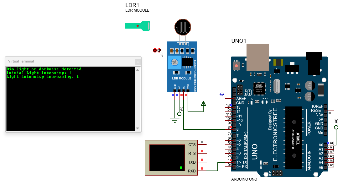
LDR Module Proteus Simulation
Here’s a snapshot of the Proteus simulation with the LDR module in action. It shows how the module reacts to different light levels, with real-time outputs that help illustrate its behavior.

Download Library
Simply click on the button to download the library. You can refer to this post for instructions on how to install the library in Proteus 8. How to Download and install Library in Proteus (electronicstree.com)
ZIP Password : electronicstree.com
If you have any requests for Arduino Module Libraries in Proteus, please leave a comment or message us using the contact form.


This is great.
I am working on a project that requires the LDR’s mathematical model.
In my project, the LDR reading is supposed to adjust automatically, based on the angle of incidence of sun rays.
Would be glad if you could help.