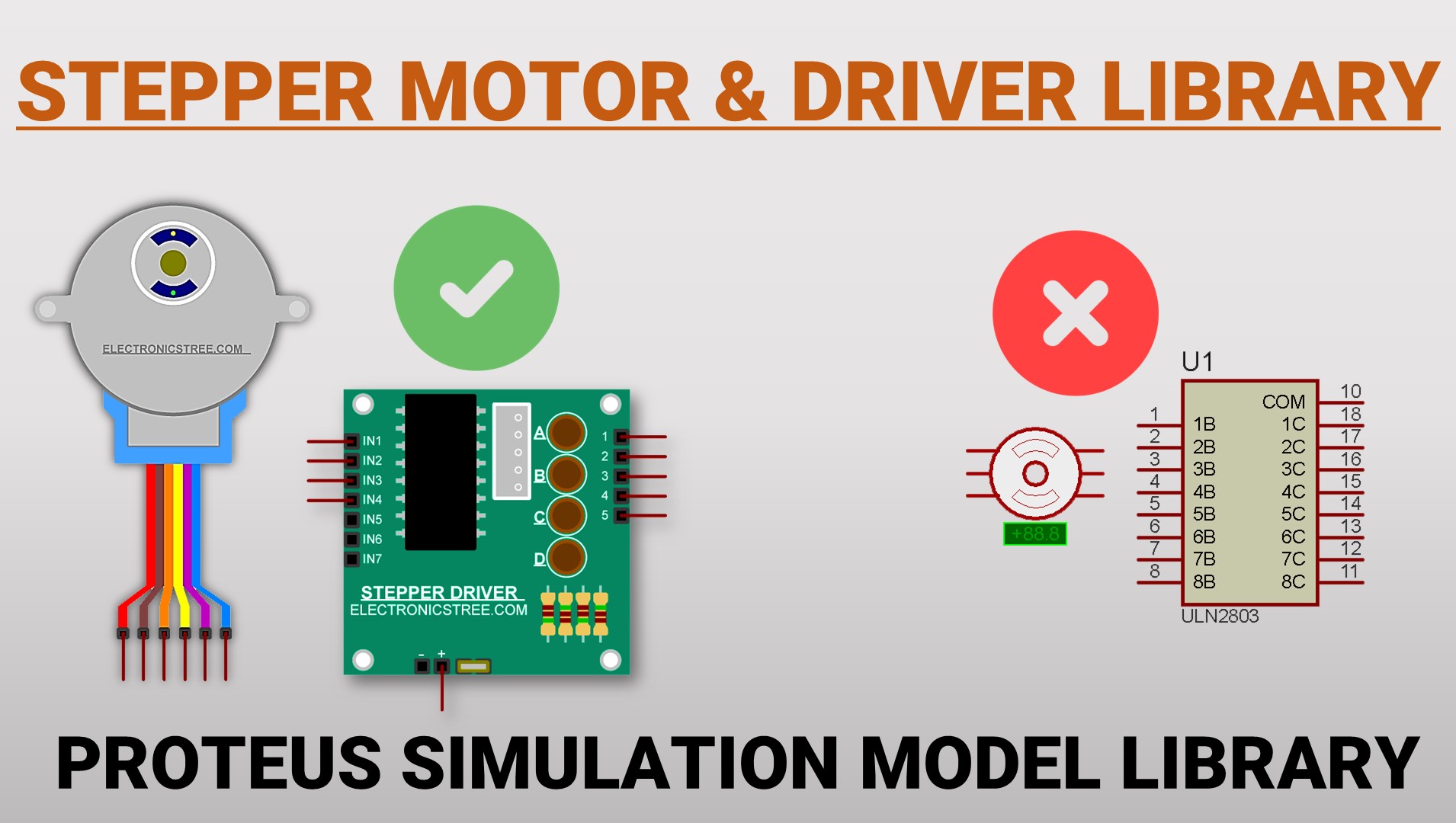
In my previous post, I shared a ULN2003 driver model for Proteus, with the goal of simplifying stepper motor simulations within the software. While Proteus does offer built-in stepper motors, their small size and less visually appealing appearance can present certain challenges:
- Limited Interactivity: The visual interaction of these motors with other components may not create a clear or engaging setup, potentially hindering the effectiveness of the simulation.
- Unclear Labeling: The lack of proper labeling on motor connections can lead to difficulties in managing stepper pin assignments within Arduino code, resulting in wasted time and potential errors.
To address these issues, I’ve created a new stepper motor model with updated graphics that closely resemble the 28BYJ stepper motor. It’s important to note that only the visuals have been modified; the functionality remains identical to the default Proteus stepper motor.
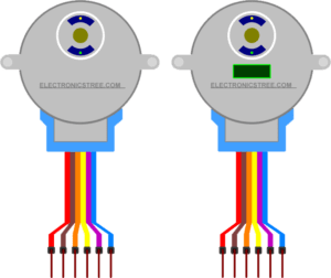
I’ve developed two versions of this model:
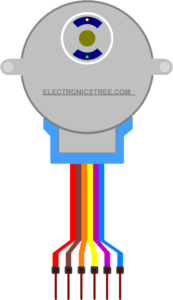
- Simple Model: This model closely mirrors the 28BYJ motor, and its animation features are drawn solely from the default Proteus stepper motor.
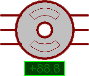
- Model with Indicator Symbol: This model incorporates the Proteus indicator symbol to visually represent the stepper motor’s step angle, a feature also present in the default Proteus motor.
For both models, I’ve replicated the connection and labeling information from a real 28BYJ motor. This ensures seamless integration with a stepper driver board, as illustrated in the hardware connection diagram.
Here is the Simulation in Proteus:

Je crois que le post(https://electronicstree.com/proteus-library-how-to-use-stepper-motor-with-driver/) précédent n’est plus disponible…
thanks
Thank you for sharing such a useful post, it is very helpful for me
i can’t unzip it because it has an error. I also do not know where to put password because the error keep coming out
Please use WinRAR to unzip the files instead of the Windows default extractor, as the library files are password protected and the default extractor will give an error without asking for the password.
This does not have a model file so it doesn’tshow up in proteus