AC Dimmer 220VAC with Arduino: Easy and Enhanced Proteus Library

AC Dimmer 220VAC with Arduino: Easy and Enhanced Proteus Library

You are currently viewing AC Dimmer 220VAC with Arduino: Easy and Enhanced Proteus Library

Introduction

An AC dimmer module is typically used to control the brightness of an AC light bulb or other AC-powered devices using an Arduino. These modules often use a technique called phase-cut dimming to control the amount of power delivered to the load. Here’s a breakdown of the key concepts involved:

Phase-Angle Control for AC Load Dimming

Phase-angle control, also known as phase cutting or leading edge dimming, is a fundamental technique for controlling the power delivered to AC loads. This technique involves delaying the activation of a triac, a powerful switch for AC power, after each zero-crossing point of the AC waveform. This delay effectively “cuts off” a portion of the sinusoidal voltage, resulting in a decrease in the average power delivered to the load. This decrease in power translates to dimming of lights, reduction in motor speed, or control of other AC devices.

AC Waveform and Zero-Crossing:

The AC waveform is a sinusoidal wave that oscillates back and forth 50 or 60 times per second depending on your location. Each cycle of the wave has two zero-crossing points, where the voltage passes through zero, neither positive nor negative. These points mark the transitions between positive and negative half-cycles of the waveform.

Triac and its Activation:

A triac is a bidirectional switch that can control the flow of AC current. However, it does not turn on automatically. It requires a trigger signal to initiate conduction. This trigger signal can be a voltage pulse at the gate terminal of the triac.

Phase-Angle Control and Cut-Off Portion:

Phase-angle control involves precisely delaying the trigger signal applied to the triac after each zero-crossing of the AC waveform. This delay can be expressed as a phase angle, measured in degrees. The longer the delay (higher phase angle), the greater the portion of the sine wave that is cut off before the triac starts conducting.

Power Reduction and Dimming:

By cutting off a portion of the AC wave, the average power delivered to the load is reduced. This is because the triac is only conducting for a shorter duration within each cycle. This reduction in power manifests as dimming in incandescent lights, reduced brightness in fluorescent lamps, or slower speed in motors.

Benefits of Phase-Angle Control:

Simple and efficient:ย It is a straightforward and effective way to control AC power and achieve dimming.
Wide range of applications:ย It can be used to dim incandescent and fluorescent lights, control motor speed, and regulate power to various other AC loads.
Easy implementation:ย Phase-angle control circuits are relatively simple to design and implement using microcontrollers like Arduino.

Limitations of Phase-Angle Control:

Harmonic distortion:ย Cutting off portions of the AC wave can create harmonic distortion, which is the presence of unwanted frequencies in the power line. This can interfere with other electronic devices connected to the same power grid.
EMI/RFI noise:ย The switching action of the triac can generate electromagnetic interference (EMI) and radio frequency interference (RFI). This noise can potentially affect sensitive electronic devices.
Not suitable for all loads:ย Phase-angle control is not suitable for all types of loads, especially those with inductive or capacitive components. These loads may require different control methods to achieve desired performance.

Applications:

Phase-angle control is widely used in various applications, including:

  • Dimmer switches for lights
  • Variable-speed drives for motors
  • Fan speed controllers
  • Power regulators for heating elements

AC Dimmer Module with Arduino

Components:

  • Arduino Uno
  • AC Dimmer Module
  • AC Load (e.g., light bulb, AC motor)
  • Jumper wires
  • Breadboard (optional)

Connections:

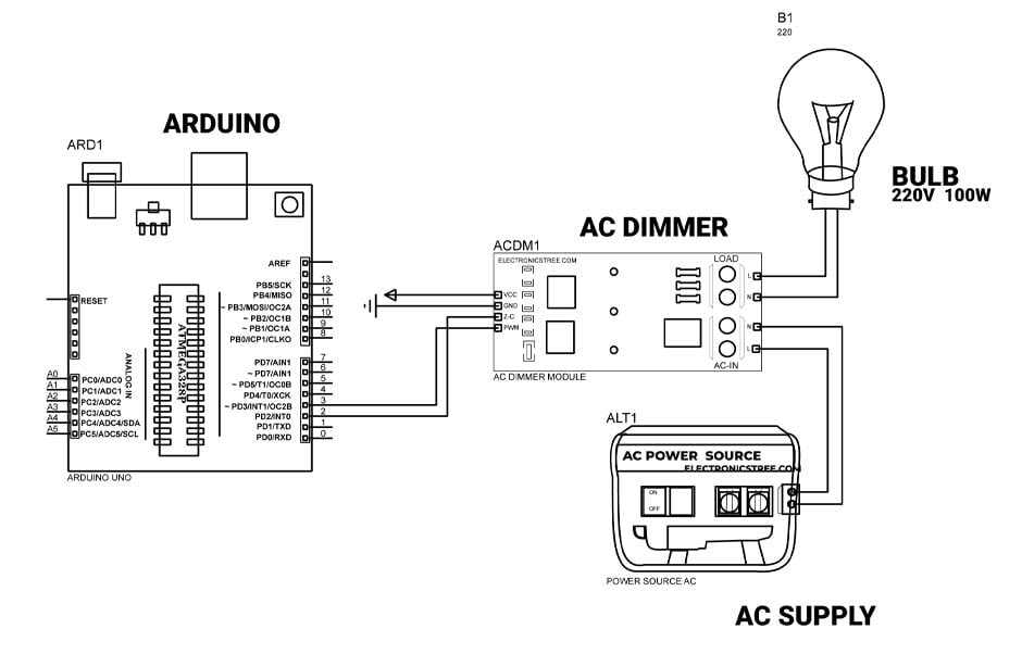
  1. Connect the VCC pin of the AC dimmer module to the 5V pin of the Arduino.
  2. Connect the GND pin of the AC dimmer module to the GND pin of the Arduino.
  3. Connect the ZC pin of the AC dimmer module to digital pin 2 of the Arduino.
  4. Connect the PWM pin of the AC dimmer module to digital pin 3 of the Arduino.
  5. Connect your AC load to the AC output terminal of the AC dimmer module.

Arduino Code:

This Arduino code is designed to control the brightness of an AC light using phase-cut dimming. It achieves dimming by delaying the firing of a TRIACย  after detecting a zero-crossing of the AC waveform. The zero-crossing detection is done using an interrupt that triggers theย zero_crosss_int()ย function.

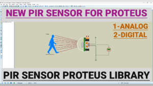
The provided code is designed to gradually control the dimming level of a light source. Here is the Simulation Result.

I have modified the code to include preset dimming levels controlled by multiple buttons. Here’s an example with four buttons, each associated with a preset dimming level:

Here is the Simulation Result in Proteus:

To control the dimming level using a potentiometer, you can replace the fixed dimming value in your code with a value read from the analog input of a potentiometer. Here’s an updated version of code to incorporate a potentiometer:

Here is the Simulation Result in Proteus:

Proteus Simulation and AC Dimmer Module Library

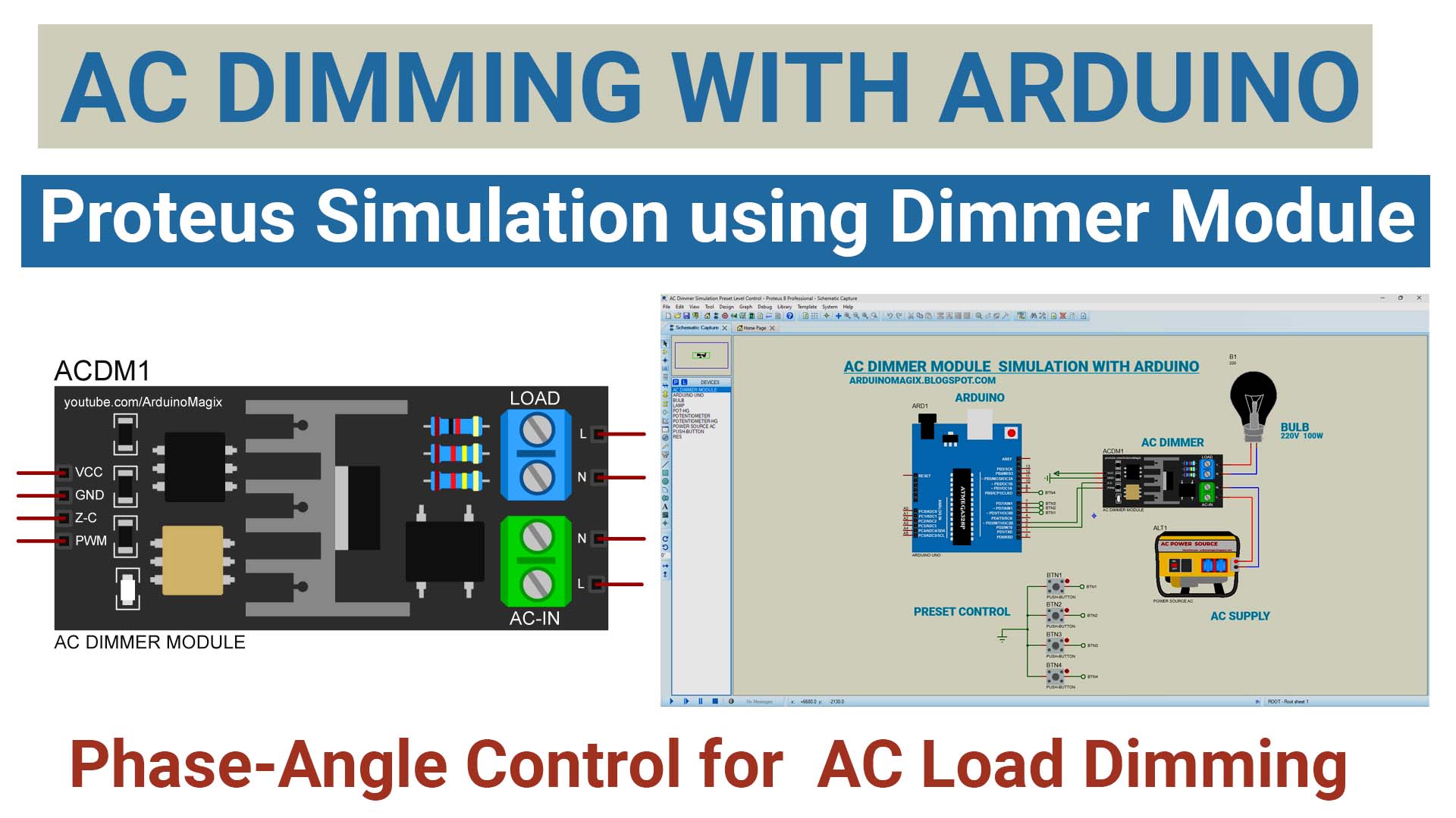
Take control of your simulated lighting with the AC Dimmer Module Library for Proteus! This Model provides you with the tools to easily design and simulate AC dimming circuit within the Proteus environment.

Extract Library Files:

  • Open the .zip file containing the model library.
  • Extract the contents, typically finding folders like LIB and MODELS.

Locate Proteus Library Folder:

  • Identify your Proteus library folder on your computer. The default location may vary based on your Proteus software version.
  • For Proteus 8 Professional, it’s often found at:
    C:\Program Files (x86)\Labcenter Electronics\Proteus 8 Professional\DATA\LIBRARY
    ย 
    ย 

Copy LIB Files:

  • Open the LIB folder extracted from the model library.
  • Copy the files within the LIB folder.
  • Paste these files into your Proteus Library Folder.

Locate Proteus Model Folder:

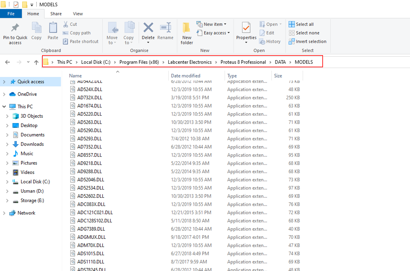
  • Find the Proteus Model folder, usually located alongside the Library Folder.
  • For Proteus 8 Professional, the path might be:
    C:\Program Files (x86)\Labcenter Electronics\Proteus 8 Professional\DATA\MODELS
    ย 

Copy MODELS Files:

  • Open the MODELS folder extracted from the model library.
  • Copy the files within the MODELS folder.
  • Paste these files into your Proteus Model Folder.
  • For certain Proteus versions, you might locate the DATA folder in a different path, such as:
    C:\ProgramData\Labcenter Electronics\Proteus 8 Professional\DATA

ย 

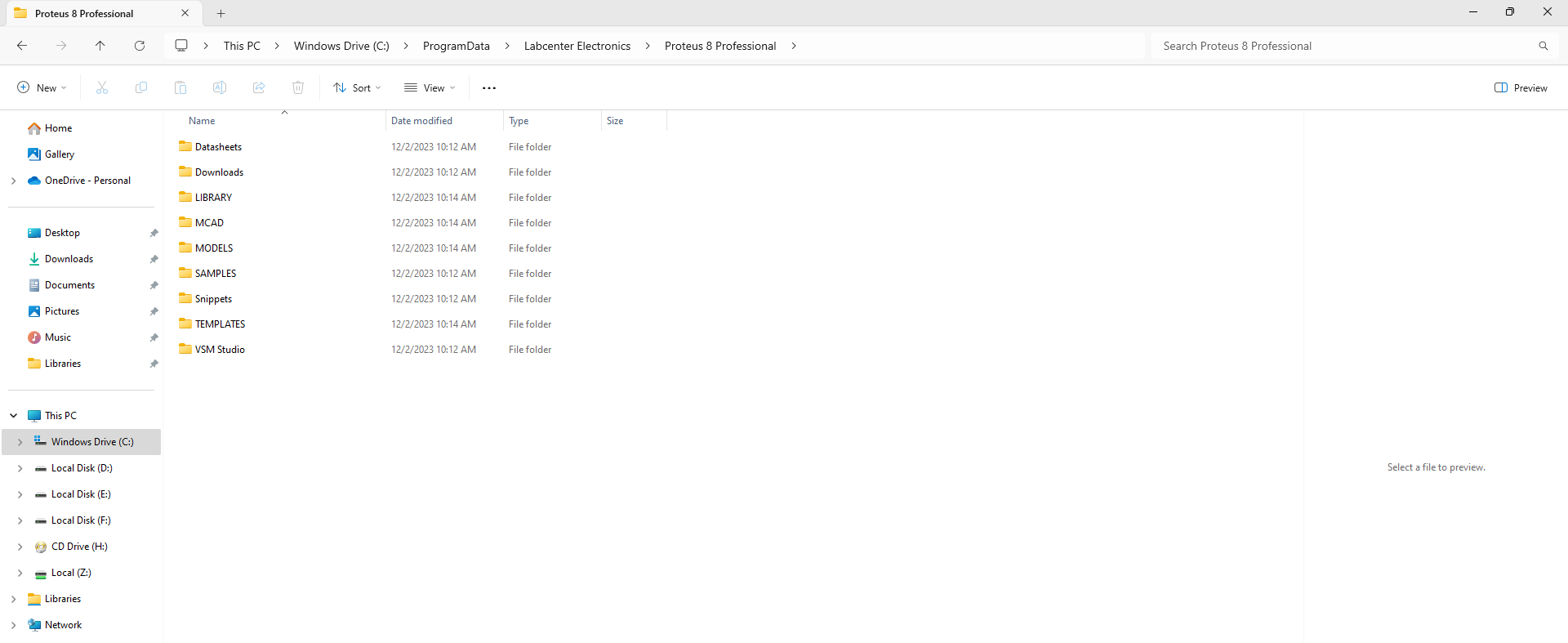
Note: The ProgramData folder could be hidden, so unhide it if needed.

Restart Proteus:

After copying the library and model files, restart Proteus to apply the changes.

Verify Installation:

  • Open Proteus and navigate to the Pick Device Window.
  • Confirm that the added model(s) are available for easy selection and integration into your projects.

Download Library

Simply click on the button to download the library. You can refer to this post for instructions on how to install the library in Proteus 8.ย How to Download and install Library in Proteus (electronicstree.com)

Please wait 120 seconds: after that, your download will begin โณ

ZIP Password : electronicstree.com

If you have any requests for Arduino Module Libraries in Proteus, please leave a comment or message us using theย contact form.

Leave a Reply