Easy Guide on Proteus and Blender : Engaging 3D Sound Visualizer

Easy Guide on Proteus and Blender : Engaging 3D Sound Visualizer

You are currently viewing Easy Guide on Proteus and Blender  : Engaging 3D Sound Visualizer

Proteus and Blender - Introduction.

Imagine a powerful duo: Proteus and  Blender. Proteus, a tech-savvy electronics tool, and Blender, a nifty 3D design buddy. Together, they create a super team for folks into making things with circuits and cool visuals.

So, Proteus and Blender does this awesome thing where it helps you play around with electronic stuff virtually, making sure everything works as it should. Now, enter Blender, the 3D magic-maker. When these two team up, you can not only make sure your electronics are top-notch but also see them in 3D – like, for real!

Concept.

The collaboration between Proteus and Blender unfolds through this scenario. Initially, we simulate Arduino and a sound sensor in Proteus. The sound sensor captures audio input from a PC, such as from your headphones or an audio file. Subsequently, it relays the sound data to the Arduino. The Arduino, in turn, transmits this value from Proteus to Blender via serial communication, facilitated by BlendixSerial.  Within Blender, we craft a 3D Sound Visualizer, animating it with the data received from Proteus.

Components.

Ready to dive into the Proteus and Blender project? Here’s what you’ll need:

  1. Proteus Software.
  2. Sound Sensor Module – Proteus Library.
  3. Arduino Board or Atmega328 Model – Proteus 
  4. Blender Software.
  5. blendixserial – Blender Addon.
  6. Blendixserial – Arduino Library.

Virtual Linking.

Proteus and Blender - Virtual Connection:

To connect Proteus and Blender, a virtual COM port emulator is required. This software program replicates the behavior of a physical serial port (COM port) on your computer. Notable options for Virtual Serial Port software include tools such as Virtual Serial Port Emulator (VSPE), com0com, and Eltima Virtual Serial Port Driver. You are free to choose any of these based on your preference.

Proteus Setup.

Sound Sensor for Proteus:

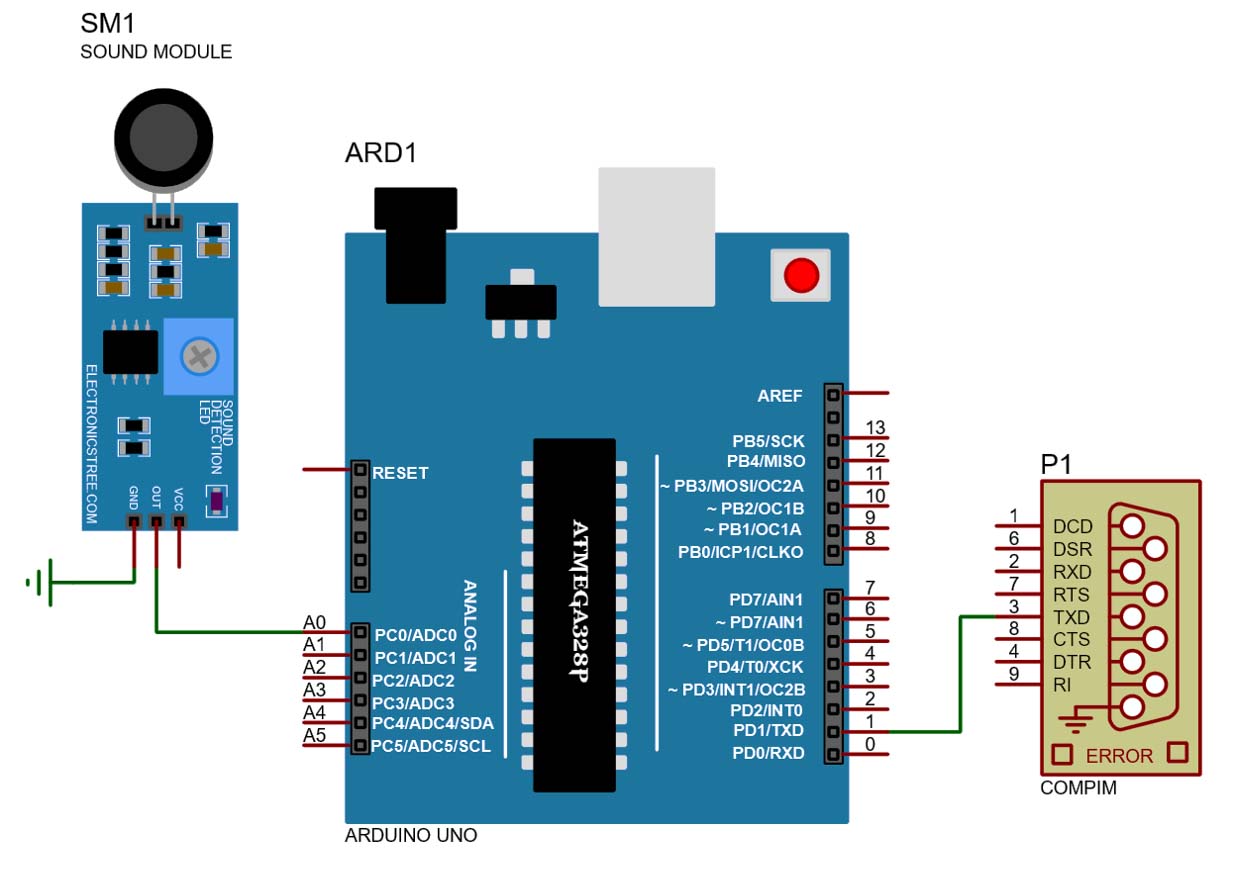
Simulating the Arduino and sound sensor in Proteus has already been covered in the previous post, so I won’t repeat it here. You can refer back to that if needed. However, in this post, I’ll delve into the additional features and functionalities this project will offer.

Sound Sensor Setup in Proteus

Previously, I mentioned using the PC’s audio input, like your microphone, as the sound source. This time, we’ll add another layer of flexibility by incorporating an audio file from your PC as well, achieved through a simple trick using VB cable Application.

Blender Setup.

blendixserial - An addon and Library:

Blendixserial A key component of this setup, it is a Blender add-on, and there is also a separate library for Arduino with the same name. If you didn’t know about this amazing add-on and library, check out this video for a clear understanding. After installing the BlendixSerial add-on, we need to create a 3D model to visualize our sound sensor data.

Creating a Basic 3D Sound Visualizer in Blender:

  • Open Blender and start a new project.
  • Select the default cube and scale it to 0.15 on the z-axis.
  • Apply the array modifier to the cube.
  • In the relative offset settings, set the z-axis value to 1.
  • Enable the constant offset option and set the z-axis value to 0.5.
  • Adjust the “count” field to increase or decrease the number of cubes along the z-axis.
Proteus and Blender : Creating a Basic 3D Sound Visualizer in Blender
Creating a Basic 3D Sound Visualizer in Blender

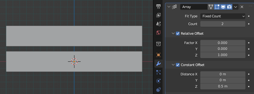
Now we need to animate these count values using sound data received from Proteus. However, we cannot directly apply the incoming values to the modifier’s count values because the Blendixserial addon only animates object transform properties. The solution is to employ Blender’s drivers. 

Animating 3D Sound Visualizer Model:

Let’s implement this solution:

  • Begin by inserting an empty object. I’ll use an empty single arrow for this example.
  • Navigate to the Properties tab and position your cursor over the z-axis of the location property.
  • Right-click to open a new window.
  • Within the new window, select the option labeled “Copy as New Driver.”
  • Select the cube you want to animate.
  • In the modifier tab, place your cursor in the count field.
  • Right-click and choose the “Paste Driver” option.
  • The count field will now be animated.
  • When you move the empty arrow along the z-axis, the array count will automatically increase in response.

Implementing Dynamic Color Effects:

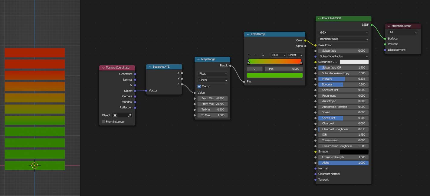
We’ll use the data from Proteus on this arrow to update the count values. Next, let’s add color effects to our 3D visualizer. Now, the problem is that I want the color of these cubes to change based on their height. As the height of the object increases or decreases, the color should change accordingly, but I’m not sure how to do it. Luckily, I found a solution on blender.stackexchange.com. After some struggle, I managed to do it. Here’s the node tree for the cube material.

Material-Node-Tree
Material-Node-Tree

Arduino Code.

Here is the complete code for sending the sound sensor values from Proteus to Blender using the BlendixSerial Arduino library.

Simulation and Visualizing.

First, ensure that you have created the virtual COM ports. After that, in Proteus, check the port settings for COMPIM. Make sure you have selected one of the virtual COM ports you created. In Blender, go to the tool panel and set the second virtual COM port, and match the baud rate with the one set in Arduino. Click on the connect button, and the BlendixSerial panel interface will appear.

Object selection and running the simulation:

In the Object tab, select the empty, and for property and axis, set it to “location” and “z.” Click on the “start movement” button, and also in Proteus, start the simulation. As soon as the simulation starts, the array value is set to 0 according to the sound sensor value because the sound sensor has no sound input. When the audio file starts, the sound sensor gives the output, and Proteus sends it to Blender, and our voice unit model responds accordingly.

Adding More Voice Unit Models:

To add more units, you can duplicate this cube and align them according to your choice. After that, delete the driver from the count values and apply the new driver for count values for the x and y axes from the empty arrow. Now, when you adjust the arrow’s x and y-axis values, the array count values will change accordingly, and you can observe the response.

Updated Arduino Code:

 Let’s modify the code. In the coordinate function, add the x and y values by using a multiplying factor. You can adjust this factor to increase or decrease the cube array relative to the original value, which is 15.

If you want to increase it further, you can use the 2nd and 3rd objects in the add-on using the same method.

Blender File.

You can download the Blender file by clicking the above download button. ZIP Password: electronicstree.com

Visit for more guides on Proteus and Blender projects. If you have any questions or suggestions regarding Proteus and Blender interfacing, please leave a comment.

Leave a Reply