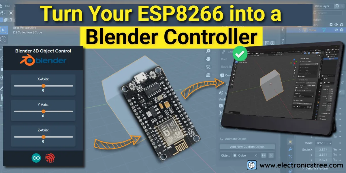
This tutorial shows you how to create a simple ESP8266 web interface to control 3D objects in Blender. You’ll send real-time updates to Blender using HTTP requests, allowing you to adjust and manipulate your 3D models interactively. Building on what we’ve already learned about Arduino and Blender basics, this guide takes things further by integrating the ESP8266 microcontroller with Blender for hands-on, interactive control. Let’s bring your models to life!
ESP8266 Web Interface: Concept Overview
The goal is to create an interactive system where you can control Blender’s 3D objects using a web interface hosted on an ESP8266 microcontroller. Here’s how it works:
ESP8266 as a Web Server
The ESP8266 acts as a WiFi-enabled web server. It hosts an HTML page with UI elements for controlling the coordinates of a 3D object. Users connect to the ESP8266’s WiFi network and access this esp8266 web interface page through a browser.
User Interaction
The esp8266 web interface allows users to adjust sliders representing the object’s position along the X, Y, and Z axes. As you move the sliders, the updated values are sent as HTTP GET requests to the ESP8266.
Processing Slider Data
The ESP8266 receives these values and processes them using its onboard code. The data is then formatted into a string using the blendixserial library.
Serial Communication with Blender
The ESP8266 sends the formatted data to Blender over a serial connection (via USB). Blender listens for this serial input and applies the received values to manipulate the corresponding 3D object in real time.
Real-Time Feedback
The system creates a seamless feedback loop, allowing you to see changes in the Blender viewport as you adjust the sliders on the web interface.
Components
Here’s a list of the key components required for this ESP8266 and Blender integration project:
- ESP8266 Microcontroller ( I will use the NodeMCU )
- Blender
- blendixserial add-on: Used to listen for serial data and apply the transformations to 3D objects.
- Arduino IDE
- ESP8266WiFi: For handling WiFi connectivity.
- ESP8266WebServer: For setting up the web server to host the sliders.
- FS (SPIFFS): For storing the HTML files on the ESP8266.
- WiFiClient: To handle communication over the WiFi network.
- blendixserial: Formats and sends data from the ESP8266 to Blender.
- USB Cable
HTML File for an ESP8266 Web Interface
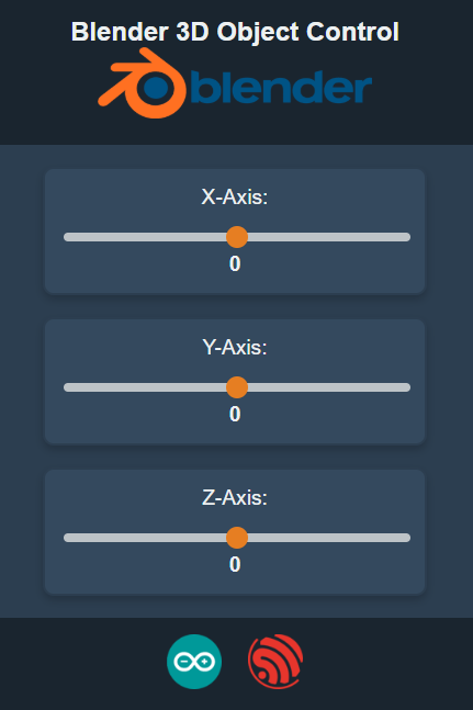
Here’s how I set up my 3D control interface. First, I create an HTML file, where I set up the sliders for the X, Y, and Z axes. Each slider is connected to a special JavaScript function called sendData(). This is where the magic happens! Whenever someone moves a slider, sendData() is triggered instantly.
Inside the sendData() function, I do a few things:
- Grab the slider values: I read the current position of each slider.
- Build the request: I create an HTTP GET request, sending the new slider positions to the program.
- Show the changes: I update the display to reflect the current slider values, giving the user instant feedback.
And that’s it! This setup ensures the esp8266 web interface looks great on any screen size and keeps everything consistent. The real-time updates make it super responsive and easy to use. please make sure to save the code in a file named index.html.
Web Server for ESP8266 Web Interface
Here’s how I set up the ESP8266 code to make everything work seamlessly. I started by including the essential libraries: ESP8266WiFi for handling WiFi connections, ESP8266WebServer for setting up a web server, FS for managing files stored on the ESP8266, and blendixserial to send control data to Blender. With these in place, I created a web server on port 80 that would host the interface and handle slider updates.
Next, I configured the ESP8266 to run in Access Point mode, allowing devices to connect directly to it without requiring an external network. I gave the network the name "electronicstree.com" for easy identification. The web page, index.html, was stored on the ESP8266 using SPIFFS, a lightweight file system. This file system was mounted at startup, enabling the server to read and serve the HTML file whenever a user connected to the device.
The server’s functionality was straightforward yet effective. When a user accessed the root URL (/), the server fetched the index.html file from flash storage and displayed it in the user’s browser. The sliders on this page allowed users to adjust the x, y, and z values, which were then sent back to the ESP8266 through an HTTP GET request to the /sliders endpoint. The ESP8266 processed these values, updated the blendixserial object, formatted the data, and sent it to Blender via the serial connection, enabling real-time 3D object control.
To keep the system running, I called server.begin() to start the server and used server.handleClient() in the loop() function to continuously process incoming requests. This setup ensured the ESP8266 acted as a WiFi hotspot, a web server, and a bridge between the web interface and Blender. The result was a responsive and efficient system that allowed users to control Blender 3D models interactively in real time.
SPIFFS Uploads with Arduino IDE 2.x
The Sketch Data Upload tool, used to upload files to the ESP8266 filesystem (like SPIFFS), is specifically designed for the older 1.x series of Arduino IDE. It doesn’t natively support the 2.x series, as the architecture for IDE 2.x has changed. Arduino IDE 2.x has a completely different backend built on Electron. It doesn’t support the old plugin system, so tools like the Sketch Data Upload tool won’t work out of the box.
I found the Arduino SPIFFS Uploader for Arduino IDE 2.x on GitHub. Here is a tutorial on the ESP8266 SPIFFS upload system with Arduino IDE 2 that you can check out.
After uploading the folder/web files, you can upload the Arduino sketch (the .ino file) to the ESP8266 as usual. Click on the Upload button in the Arduino IDE to upload the ESP8266 code.
ESP8266 Web Interface and Blender Connection
After uploading the code, we now need to connect the ESP8266 to Blender via serial. Make sure the serial monitor of the Arduino IDE is closed. Open Blender and press ‘N’ to open the side panel. You will find the blendixserial addon tab (in your case, please make sure to install the blendixserial addon).
Now, select the port and baud rate of your ESP8266 board and establish the serial connection. After setting the mode to receiving, use the option to add a new object and select the object. Currently, I’m using the default cube for this. In the preferences menu, select ‘Property’ and ‘Axis Selection.
After that, enable movement via the start button. Now, connect your device (any device that has a browser) to the ESP8266 network. I will connect my Android device to the ESP8266. Once connected, open the browser and type the ESP8266’s default IP address: 192.168.4.1. A UI page will open, containing sliders for the object’s axis. And there you go!”


hayan19