A rotary BCD switch with positions ranging from 0 to F (hexadecimal) provides output values in a 4-bit binary format representing hexadecimal digits. This type of switch is commonly used in applications requiring the selection of values from 0 to 15.
Introduction to BCD Switches
A BCD (Binary-Coded Decimal) switch is a device designed for selecting specific numeric values in electronic systems. It operates by assigning each switch position to a unique BCD value, usually defined by a 4-bit binary code. These switches find frequent use in scenarios where users manually input numeric data. For instance, they are integral in setting device addresses within communication networks, inputting values into counters, and configuring parameters in digital circuits. This methodical selection process ensures precise and reliable data entry, essential for various electronic applications.
How BCD Switches Work
Rotary BCD Switch:
In a rotary BCD switch, there’s a knob that you turn to select different positions. Each position directly corresponds to a decimal value from 0 to 9.
Output: It provides a binary representation of the selected decimal value through four output pins. For instance, setting the switch to ‘5’ outputs 0101 in binary.
In this article, I’ll be discussing the use of a MICRO-DIP rotary BCD switch from EECO. This switch is designed to offer precise functionality in electronic applications, combining compact design with robust performance.
Micro-DIP Printed Circuit Board Switches
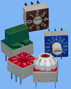 The 3500 Series MICRO-DIP® is a compact rotary DIP switch designed to meet the demands of modern automated soldering and cleaning processes. It offers several key features:
Low profile and fully sealed design ensure reliability in harsh environments. Direct decimal to binary conversion simplifies addressing PROMs and configuring microprocessor-controlled devices. Available in six binary and decimal codes, with options for extended shafts and right angle orientations to accommodate diverse design needs. Backed by EECO’s exclusive Lifetime Warranty, ensuring long-term peace of mind for users. All products in the 3500 Series are Lead-Free and fully RoHS compliant, aligning with environmental standards.
This switch series provides a user-friendly solution for precise configuration in various electronic applications, combining durability with flexibility in design.
Rotary BCD Switch with 16 Positions
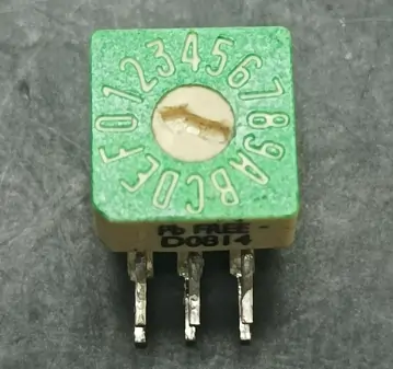
Rotary BCD switches come in two types: top adjust and side adjust models. The switch I’m using is a 16-position side adjust model. You can find all the information, including electrical, mechanical, environmental, and material specifications, in the datasheet.
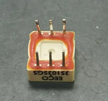
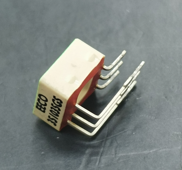
This switch has 6 terminals in total. Four of these terminals are labeled 1, 2, 4, and 8, while the remaining two are marked as C, which stands for the common terminal. Because it is a side-adjust model, I had to cut its right-angle terminals and straighten them to use it on the breadboard.
Truth Table of Rotary BCD Switch
This image is from the datasheet and shows how a rotary BCD switch with 16 positions corresponds to hexadecimal values (0 to F). It explains how the common terminal (C) connects to the four output terminals (1, 2, 4, 8) depending on which position is selected. These output terminals represent binary values.
The table columns are organized as follows:
- DIAL: This column represents the dial position, which ranges from 0 to F in hexadecimal.
- 1, 2, 4, 8: These columns represent the binary output bits. Each bit position corresponds to a binary value (1, 2, 4, 8).
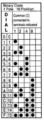
Each row of the table shows the binary output for the corresponding dial position. When the switch is set to a particular position, the common terminal (C) is connected to the terminals indicated by the black dots in that row. These connections determine the binary output value.
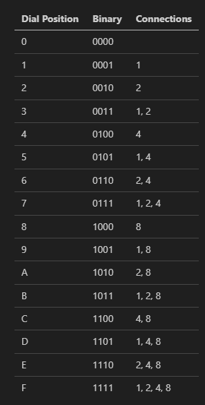
I have simplified the truth table, which represents each position of the rotary BCD switch. It shows the corresponding binary representation and the connections to the common terminal (C) for each position. If you connect the common terminal (C) of the rotary BCD switch to the positive supply (e.g., Vcc), the connections column in the truth table indicates the pins that will be HIGH when the switch is set to that position. The remaining pins will be LOW.
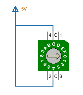
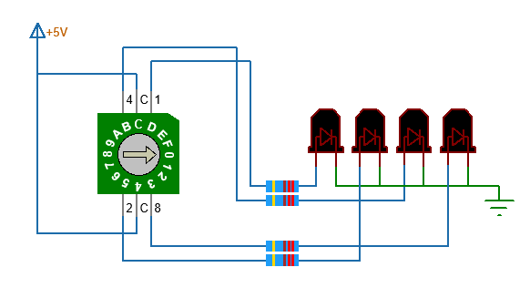
Circuit Connection - How to use it without Arduino
This wiring setup enables you to visually verify the output of the rotary BCD switch by observing which LEDs light up. Each position of the switch corresponds to a specific combination of LEDs being on or off, representing the binary value of the selected position.
How to use it with Arduino
When using a BCD switch with an Arduino, you can read the state of each pin using the digital pins. Then, you can directly multiply each value by its corresponding weight and sum these products to obtain the decimal value.
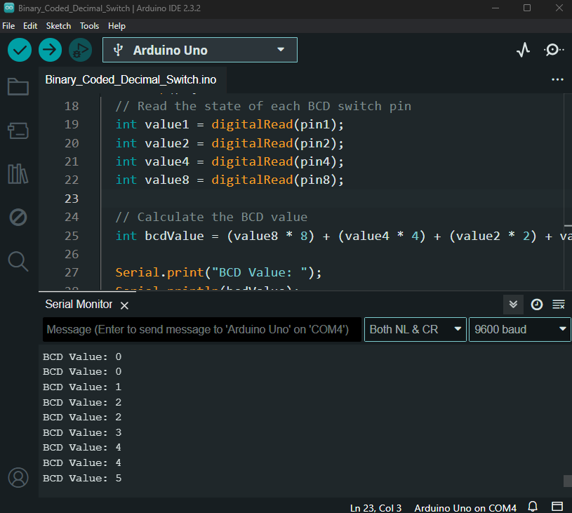
Here is a video demonstration showing the setup of the rotary BCD switch on the breadboard and how it operates.


If it has 16 positions it is not BCD (Binary Coded Decimal). Decimal = 10. 16 Positions is Hexadecimal, base 16.
You’re right, thanks for the correction.