SPICE fundamentals basically means the basic ideas behind SPICE. SPICE Fundamentals are the basics of using SPICE, a tool for simulating electronic circuits. SPICE works by using a text file called a “netlist” that describes the entire circuit. This netlist includes each component in the circuit—such as resistors, capacitors, and power sources—and shows how they’re connected.
Each component is written with simple syntax: a name, the nodes it connects to, and its value (like resistance or capacitance). SPICE fundamentals also include different types of analysis, like DC for steady-state behavior, AC for frequency response, Transient for time-based changes, and Noise for examining circuit noise.
These analyses let engineers test and understand how their circuits would perform in real life, helping to find and fix issues early in the design process. Learning SPICE fundamentals gives you the skills to explore and optimize circuits right on your computer.
SPICE Fundamentals: Its Role in Electronic Simulation
Simulation software is essential for designing and testing electronic circuits before any physical prototypes are made. At the heart of many of these tools is SPICE (Simulation Program with Integrated Circuit Emphasis), a tool that originated in the 1970s at the University of California, Berkeley.
This capability helps engineers spot potential problems and inefficiencies before building physical prototypes. Additionally, by simulating factors like temperature changes and component tolerances, SPICE not only saves time but also boosts the reliability and performance of electronic designs.
Since it first came onto the scene, SPICE has undergone significant evolution, resulting in a variety of versions and derivatives, both open-source and commercial. Here’s a look at some of the major SPICE models and their different versions:
1. Original SPICE Versions
- SPICE1 (1973): The first version of SPICE was developed by Larry Nagel and Donald Pederson. It was mainly a teaching tool and had limited capabilities.
- SPICE2 (1975): This version introduced a better numerical algorithm and incorporated improvements like nonlinear components and improved models for diodes, BJTs, and MOSFETs. SPICE2G6 was the most widely distributed version of SPICE2.
- SPICE3 (1989): A major overhaul of the original SPICE2 code, rewritten in C (SPICE2 was written in Fortran). It introduced new features like interactive simulation and better convergence algorithms.
2. Berkeley SPICE Derivatives
These are versions based on the Berkeley SPICE core code:
- Cider (CktSim): A mixed-level simulator that combined SPICE and device-level simulators for more detailed modeling of semiconductors.
- XSPICE: Developed by Georgia Tech, XSPICE extended SPICE3 by adding support for event-driven modeling, allowing mixed analog and digital simulation.
3. Commercial SPICE Tools
Over the years, many companies have developed commercial versions of SPICE with additional features and improved performance.
- HSPICE (Synopsys): A highly accurate and widely used version of SPICE for high-performance analog and mixed-signal designs. Known for its precision and scalability.
- PSPICE (Cadence): One of the earliest commercial SPICE versions, PSpice is popular for PCB and analog/mixed-signal simulation. It offers additional features for power analysis, thermal simulation, and more.
- LTspice (Analog Devices): A free version of SPICE developed by Linear Technology (now part of Analog Devices). LTspice is popular for its user-friendly interface and built-in model libraries.
- TINA-TI (Texas Instruments): A SPICE-based analog simulator provided for free by Texas Instruments. It is tailored for simulating TI’s component models.
- ISSPICE4 (Intusoft): Another commercial SPICE variant that provides enhancements for analog and digital circuit simulation.
- NGSPICE: A mixed-level/mixed-signal circuit simulator based on SPICE3f5 and Cider1b1. It is open-source and widely used for academic and hobbyist purposes.
- SmartSpice (Silvaco): A high-performance SPICE simulator with advanced features for large-scale analog circuit simulations.
- Spectre X (Cadence): A SPICE-compatible simulator known for its use in RF, analog, and mixed-signal IC designs. Spectre provides enhanced convergence and speed.
- T-Spice (Tanner EDA): Known for its integration with Tanner EDA tools, T-Spice focuses on custom IC design and layout.
4. SPICE for Specific Use-Cases
These versions include improvements or focus on specific device models:
- BSIM (Berkeley Short-channel IGFET Model): Models that are widely used for MOSFETs in advanced semiconductor nodes. Multiple versions (BSIM3, BSIM4, BSIM-CMG for FinFETs, etc.) are incorporated into SPICE simulators.
- EKV (Enz-Krummenacher-Vittoz): A compact model for MOSFETs, primarily focused on low-power design.
5. Modern Versions and Extensions
- ADMS: A code generator that compiles Verilog-A models into C code that SPICE simulators can understand.
- Verilog-A/AMS Support: Many modern SPICE tools include support for Verilog-A/AMS models, which allows users to describe custom devices and systems using high-level behavioral models.
- FastSPICE (SmartSpice Pro, AFS, etc.): These are specialized versions of SPICE optimized for very large analog and mixed-signal designs, offering faster simulation speeds at the expense of accuracy (e.g., SmartSpice Pro by Synopsys, AFS by EDA Solutions ).
SPICE Fundamentals: Structure and Netlist
SPICE software interprets a digital description of a circuit and performs calculations to predict how the circuit would behave. Think of SPICE like a “virtual circuit lab.” You tell it which components you want (resistors, capacitors, transistors, etc.) and how they connect, and it shows you how they’ll work together.
Structure: How It Works
Here are the main elements of SPICE structure:
- Components: SPICE includes models of common circuit elements such as resistors, capacitors, inductors, diodes, and transistors. These elements make up the building blocks of a circuit. Every component type in SPICE has its own identifier:
Component Type Identifier:
Rfor resistorCfor capacitorLfor inductorVfor voltage sourceIfor current source- And others for different components.
Name:
This is a unique identifier for the component within the netlist. It typically combines a letter corresponding to the component type and a number or descriptive label. The name helps distinguish this component from others in the circuit.
- Nodes: A node is any point where two or more components connect, similar to a junction on a circuit board. SPICE uses nodes to determine where each component is connected in the circuit. Each node is a point in the circuit, labeled with a name (like
N1,N2, or any descriptive name).
- Connections: Each component connects to two nodes, just as you’d connect wires between parts on a physical circuit. This structure of nodes and connections allows SPICE to understand the circuit layout and analyze how signals flow through it.
- Value or Parameters: This part specifies the characteristic of the component. For resistors, this would be resistance in ohms. For capacitors, it would be capacitance in farads. For voltage sources, it would be the voltage level. The format may vary by component type (e.g., numeric values, units like
kfor kilohms,ufor microfarads).
By combining these components and connections in a structured format, SPICE effectively recreates the circuit electronically and allows you to analyze it in multiple ways.
Using a generic template, the syntax would look like this:
<TypeIdentifier><name> <node1> <node2> <value>
R1 1 2 1k
R: This is the identifier for the resistor, named1.1: This is the first node (where the current enters).2: This is the second node (where the current exits).1k: This indicates that the resistor has a resistance of 1 kilohm.
The Netlist: Describing the Circuit
A netlist is a text file that details the circuit layout in a format SPICE can read. Think of it as a list of components are in the circuit, their values, and how they’re connected. In simple terms when you compile all these component definitions together in a SPICE format, it’s called a netlist.
Key Elements in a SPICE Netlist:
- Comments: Lines beginning with
*are comments for easy readability. - Component Definitions: As explained above like Resister R1, each line defines one component.
- Analysis Commands: These specify the types of simulation to run (e.g.,
.opfor operating point,.tranfor transient,.acfor AC analysis). - End of Netlist: The
.enddirective marks the end of the netlist.
- Comments: Lines beginning with
Example of a Simple Netlist:
*  Capacitor Charging Circuit Netlist
V1 1 0 DC 5
R1 1 2 1k
C1 2 0 10u
.TRAN 1ms 50ms
.END
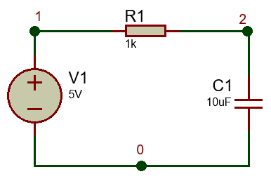
Here, we have a simple circuit with a resistor (R1), a capacitor (C1), and a voltage source (V1) . SPICE uses this netlist to interpret the circuit structure and run simulations on it.
Schematic vs. SPICE Netlist
When learning to create netlists, it’s helpful to think of the process in two stages: first, drawing the circuit on paper or using an editor, and second, creating a SPICE netlist. This analogy can clarify how to translate a visual representation of a circuit into a format that a simulation program like SPICE can understand.

When you draw a schematic, you connect components using lines that represent wires. Label the connections with nodes (like 1, 2, etc.) to show where the components meet. This step helps you visualize how the entire circuit functions.
After that, the next step is to convert your visual design into a SPICE netlist. This netlist describes the same circuit you just drew. Each component from your schematic corresponds to a line in the netlist:
- Voltage Source: This will specify the voltage and its nodes.
- Resistor: You define its value and the nodes it connects.
- Capacitor: Similarly, you include its capacitance and connections.
V1 1 0 DC 5
5V DC voltage source connected between node 1 and ground (0)
R1 1 2 1k
1k ohm resistor between node 1 and node 2
C1 2 0 10u
10 microfarad capacitor between node 2 and ground (0)
Complete circuit component definitions:
V1 1 0 DC 5
R1 1 2 1k
C1 2 0 10u
Each line in the netlist directly matches the components and connections from our schematic.
This circuit is essentially the same as the capacitor charging circuit example provided earlier, but we’ve used different node names. As I mentioned, we’ve completed one of the four key elements of the SPICE netlist: the component definitions that describe our circuit. Now, we can proceed to add the remaining elements.
SPICE accepts the first line of the circuit file as a title line, and you can even leave it blank if you prefer.
Capacitor Charging Circuit
V1 1 0 DC 5
R1 1 2 1k
C1 2 0 10u
In this netlist, the first line acts as a circuit title line, which can also serve as a comment. You can write this line as a comment using an asterisk (*) or leave it without one.
Capacitor Charging Circuit
V1 1 0 DC 5
R1 1 2 1k
C1 2 0 10u
.end
Finally, we need to add the .end command, which tells SPICE that this is the end of the netlist.
Now that we have created our basic netlist, the next step in understanding SPICE fundamentals is to add the analysis commands, as shown in the example at the beginning of this section. While the netlist would technically be complete without these commands, they are essential for specifying the type of analysis we want to perform.
In the next section, we’ll discuss these commands in detail, including how they can be used within the netlist file or separately. After that, we’ll continue with more netlist fundamentals.
Download Free Animated Libraries for Proteus
Explore a rich collection of libraries to enhance your electronic design projects and simulations effortlessly.
DownloadSPICE Fundamentals: Types of SPICE Analysis
Once you’ve set up the netlist, SPICE can perform several types of analysis on your circuit. Each type of analysis gives insights into how the circuit would function under different conditions:
DC Analysis
DC Analysis is used to see how a circuit behaves when powered by a steady, non-changing direct current (DC) voltage. In this analysis, SPICE finds the “operating points” of the circuit, which means it calculates the steady (unchanging) voltages and currents at each point in the circuit.
This type of analysis helps you understand the basic behavior of the circuit under constant conditions. For example, it shows you the voltage at specific parts of the circuit or the current flowing through certain components when nothing is changing in time.
Transient Analysis
Transient Analysis shows how the circuit behaves over a period of time, rather than at just a steady point. SPICE simulates the circuit’s behavior from one point in time to another. This analysis can model circuits that turn on, turn off, or change due to pulses or other time-based signals.
This is important for circuits where timing matters, like digital circuits or pulse-driven systems. For instance, it lets you observe how a circuit responds when a switch is flipped on or off, or how it handles pulses (like in digital clocks or signal generators).
AC Analysis
AC Analysis is used to study how a circuit responds to alternating current (AC) signals that change in frequency. SPICE simulates the circuit’s response to AC signals over a range of frequencies. It calculates how the voltage and current react when the frequency of the signal changes.
This analysis is helpful for circuits that deal with audio or radio signals, which naturally vary in frequency. It helps engineers see how the circuit amplifies, attenuates, or alters signals at different frequencies. For example, it’s essential in audio equipment, radios, and signal processing applications.
Noise Analysis
Noise Analysis estimates the electrical “noise” generated by the circuit, which can interfere with its normal function. SPICE calculates the level of unwanted random fluctuations (noise) at different points in the circuit. These fluctuations might come from components or from the circuit’s layout.
Noise is especially problematic in sensitive circuits, like those in audio and communication devices, where clear signal transmission is essential. This analysis helps identify noise sources and see if they need to be reduced for better performance.
These analyses are the core simulations that SPICE performs to predict how a circuit will behave under different conditions. When you run each type of analysis, SPICE essentially simulates the circuit’s behavior, allowing you to see potential performance, identify issues, and make design improvements before physically building the circuit. Each analysis type gives a different perspective on the circuit’s operation, making SPICE a powerful tool for circuit design and testing.
SPICE Fundamentals: Simulation = Running one or more types of analysis
A SPICE “simulation” is essentially SPICE running one or more of these analyses to give insights into how the circuit would function in real-world conditions.
When we say “SPICE is simulating the circuit,” it usually means that SPICE is performing one (or sometimes multiple) types of analysis to model how the circuit behaves.
In SPICE, each type of analysis has its own command that you can include in the netlist to run that specific analysis. .DC for steady-state DC behavior, .AC for frequency response, .TRAN for time-based changes, and .NOISE for estimating circuit noise. Together, these commands help analyze all key aspects of circuit performance.
Netlist with Transient Analysis
To simulate the charging process over time, you’d add a .TRAN command in the netlist to set up the transient analysis:
Capacitor Charging Circuit
V1 1 0 DC 5
R1 1 2 1k
C1 2 0 10u
.tran 1ms 100ms
.end
This transient analysis command simulates the circuit over time, from 0 to 100 milliseconds with a time step of 1 millisecond.
Once the netlist is complete, we can save it in a file and load it into a SPICE simulation tool to analyze the circuit’s behavior, observe voltage and current changes over time, and verify that it operates as intended. We will do this in the next part using the SPICE simulator.


