What is a FSR Sensor?
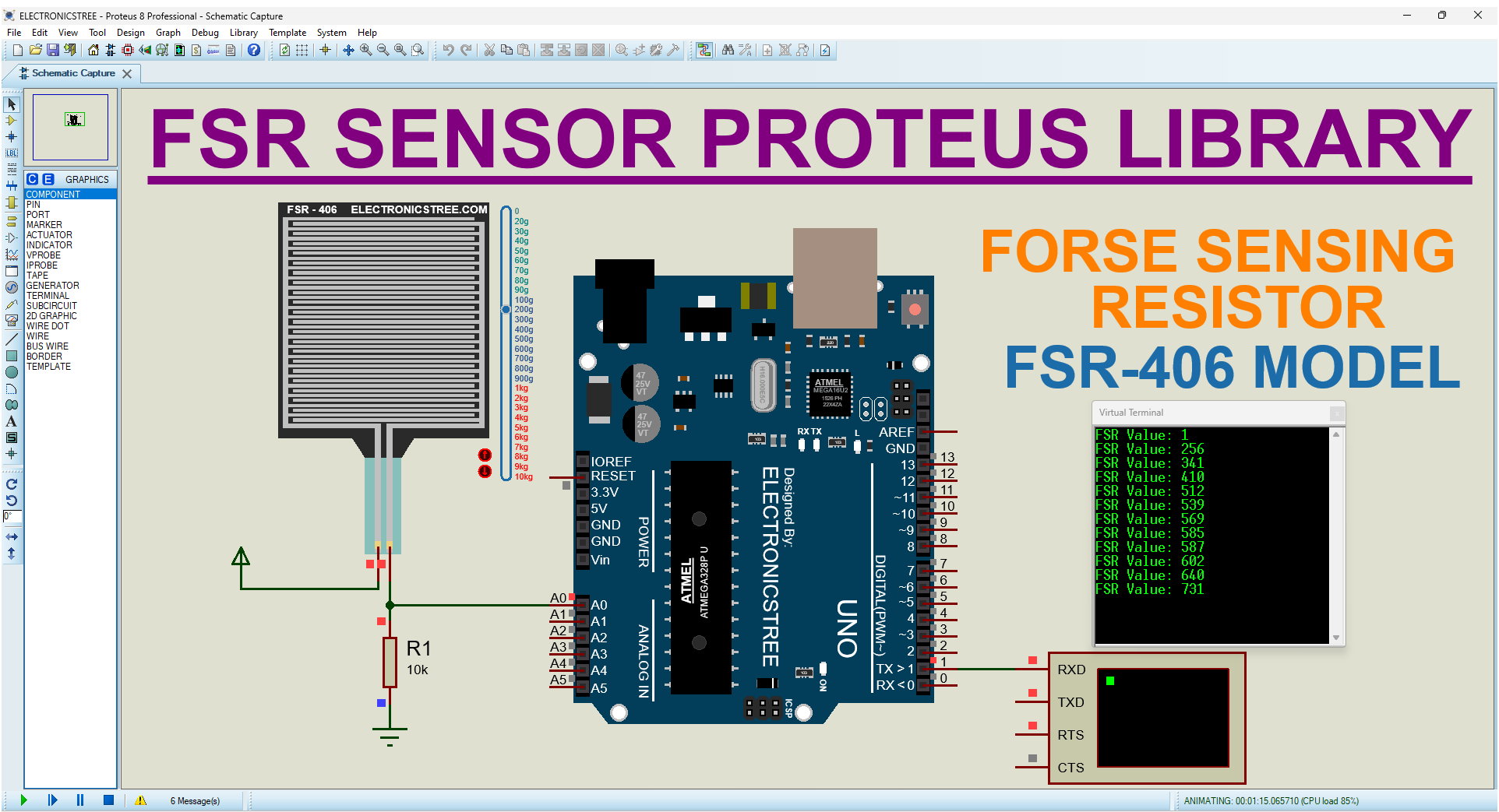
A Force-Sensing Resistor or FSR Sensor is a type of sensor that changes its resistance based on the amount of force or pressure applied to its surface. This change in resistance allows the FSR to be used as a sensor for detecting and measuring force or pressure levels. In this tutorial, we will guide you through the process of integrating the FSR sensor with Arduino in Proteus simulation using the FSR-406 sensor Proteus library.
FSR Sensor Proteus Library
In this post, I’ll be sharing the FSR model for Proteus simulation. This FSR model offers an actual FSR experience, which you can easily integrate into your projects. It features a convenient slider control for adjusting the force applied to it.
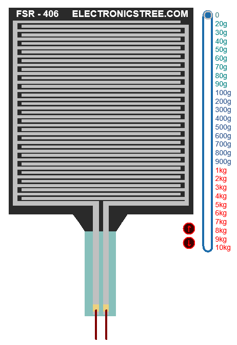
FSR Sensor Design
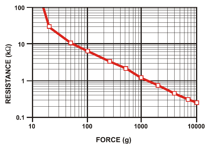
The foundation of this model lies in the graph sourced from the FSR guide document, showcasing the inverse correlation between force and resistance. This graph, which is integral to understanding the behavior of FSRs, demonstrates how as force increases, resistance decreases, and vice versa.
Log-Log Scale:
FSR graphs are typically not linear but use a log-log scale. This means both the force and resistance values are plotted on a logarithmic scale.
- This is because the change in resistance is much more dramatic at lower forces compared to higher forces.
- A linear scale wouldn’t accurately represent this behavior.
Understanding the Curve:
The curve on the graph is not perfectly straight on a log-log scale either. It often shows a steeper decline at lower forces and then flattens out as force increases.
- This is because the FSR becomes more sensitive at the beginning when pressure is initially applied.
- As more force is used, the rate of resistance change slows down.
How to use the FSR Sensor
Voltage Divider Setup:
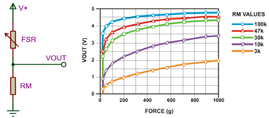
- The setup involves connecting an FSR (Force-Sensing Resistor) and a measuring resistor (RM) in a voltage divider arrangement.
- The FSR’s resistance (RFSR) changes based on the force applied to it. As force increases, the resistance of the FSR decreases, and vice versa.
Output Voltage Equation:
- The output voltage (VOUT) from this setup can be calculated using the voltage divider formula: VOUT = (V+) / [1 + RFSR/RM]. Here, V+ is the input voltage.
Force and Output Voltage Relationship:
- When you press harder on the FSR (more force):
- Its resistance (RFSR) decreases.
- This makes the output voltage go up.
- When you press harder on the FSR (more force):
Effect of Interchanging Resistors:
- If you swap the positions of RFSR and RM in the circuit, meaning the FSR is now connected to RM and vice versa:
- The output voltage behavior changes.
- Now, as force increases:
- The resistance that changes with force (i.e., RFSR) is connected to RM.
- This alters the voltage division ratio differently compared to the previous configuration.
- As a result, the output voltage decreases with increasing force.
- If you swap the positions of RFSR and RM in the circuit, meaning the FSR is now connected to RM and vice versa:
Mirror Image Effect:
- These two scenarios create mirror images of each other with respect to the line VOUT=V+/2.
- When graphed, the output voltage vs. force curve for the first configuration (FSR connected to RM) would be a reflection across the line VOUT=V+/2 of the curve for the second configuration (FSR connected to voltage source).
Proteus Simulation
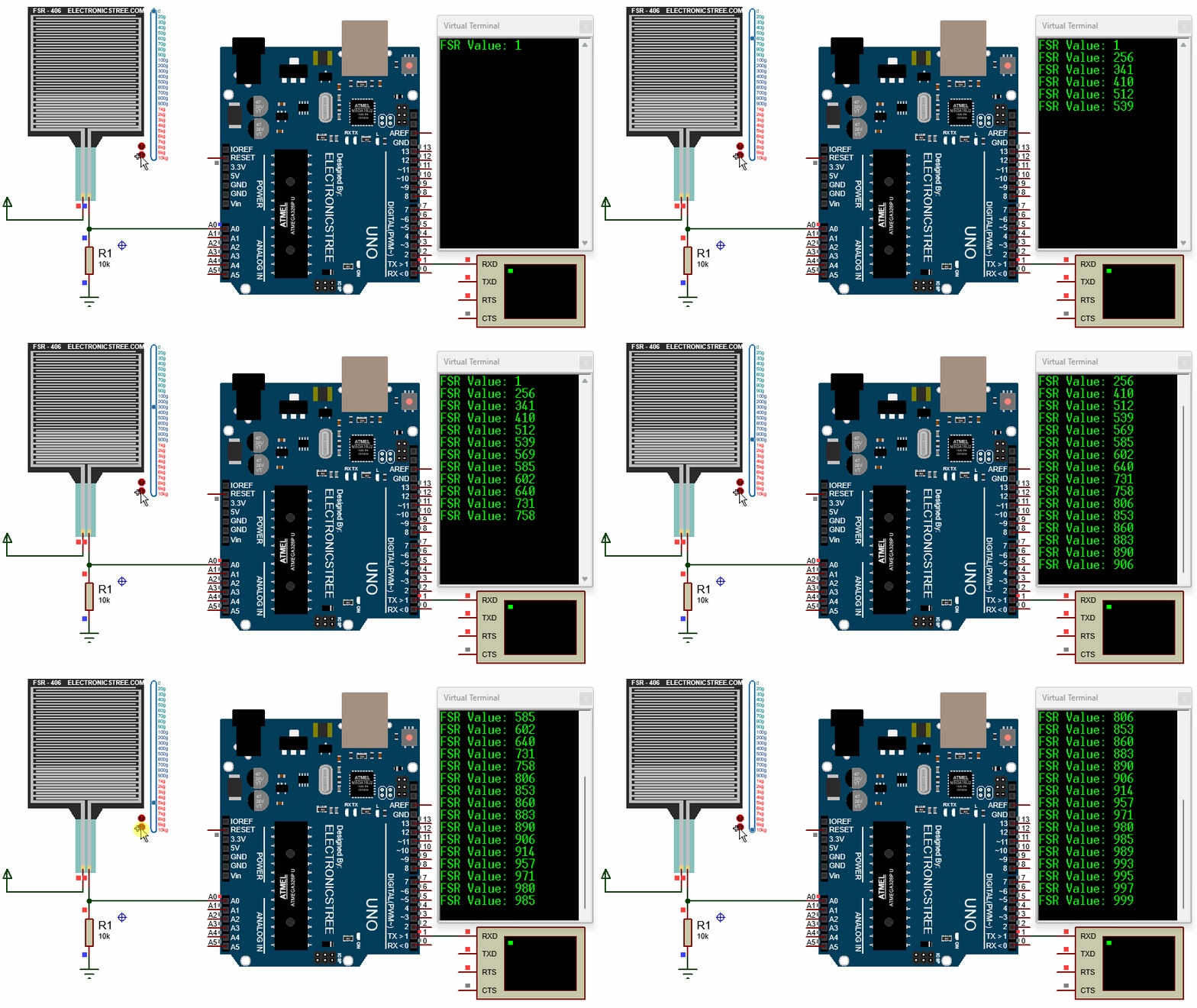
Here is the Proteus Simulation of FSR Sensor.
Arduino Code
Download Library
Simply click on the button to download the library. You can refer to this post for instructions on how to install the library in Proteus 8. How to Download and install Library in Proteus (electronicstree.com)
ZIP Password : electronicstree.com
If you have any requests for Arduino Module Libraries in Proteus, please leave a comment or message us using the contact form.
