If you’re looking for a simple way to measure AC or DC current with an microcontroller, this guide covers how to do it using the Arduino and DHR 200 C420 transducer. The DHR 200 C420 is a precise current sensor that can handle up to 200A and outputs a standard 4–20 mA signal. This signal reflects the measured current and can be easily read by PLCs, microcontrollers (with a bit of signal conversion), meters, or other monitoring systems.
LEM International is a globally renowned leader in electrical measurement solutions, widely acknowledged for its innovative transducer and sensor technologies. The DHR series of current transducers, developed for both AC and DC current measurement, epitomize this excellence.
One of the most vital features of the DHR series is the capability to perform true RMS measurements. This is especially important when dealing with non-sinusoidal currents such as those generated in Variable Frequency Drives (VFDs) or in phase-controlled systems utilizing Silicon Controlled Rectifiers (SCRs). The true RMS capability ensures that measurement accuracy is maintained even with distorted waveforms, which is critical in applications like switching power supplies and electronic ballasts.
DHR 200 C420 Specifications
The DHR series is available in several configurations, catering to primary current measurement ranges from as low as 100 A up to 1000 A. For instance, the DHR-C420 model is available with different nominal primary current ratings 100, 200, 300, and 400 A.
Depending on application needs, LEM’s transducers offer multiple output signal types:
- 4–20 mA current loop output (DHR-C420): Highly robust for industrial control applications.
- Voltage outputs: 0–5 VDC (DHR-C5) and 0–10 VDC (DHR-C10) options are provided, with explicit load requirements to ensure proper functioning.
| Feature | Description |
|---|---|
| Measurement Type | True RMS measurement of AC/DC current |
| Input Range | Models available for 100A to 200A current |
| Output Signal | 4–20 mA current loop (DHR-C420 model) |
| Output Load | Maximum 300 Ω at 24 VDC |
| Power Supply | 20–50 VDC required (typically 24 VDC) |
| Accuracy | ±1% Full Scale |
| Frequency Range | DC to 6 kHz (±1 dB) |
| Response Time | 150 ms to 90% of step change |
| Operating Temp | -40 to +70°C |
| Output Isolation | 4 kV (IEC 61010-1 standard) |
| Mounting | Surface-mount using M4 screws (tightening torque 0.75 Nm ±20%) |
For more information about the DHR 200 C420, you can visit the official LEM website.
You might also want to check out resources on using Arduino with current sensors like the ACS712, which is another popular option for measuring current in DIY electronics projects.
ACS712 Current Sensor: Easy and Enhanced Proteus Library – ELECTRONICS TREE
Arduino and DHR 200 C420
To measure the current signal with Arduino and DHR 200 C420, you must convert the current into a voltage using a shunt resistor. Here’s how to choose a resistor value:
- Choosing a Resistor Value:
Using Ohm’s law (V = I × R), if you choose a resistor of 250 Ω, then:- At 4 mA: 4 mA × 250 Ω = 1.0 V
- At 20 mA: 20 mA × 250 Ω = 5.0 V
With a 220 Ω resistor:
- At the low-end, 4 mA produces a voltage of:
0.004 A × 220 Ω = 0.88 V - At the high-end, 20 mA produces a voltage of:
0.020 A × 220 Ω = 4.4 V
This voltage range is well within the Arduino’s analog input limits and provides resolution while keeping some headroom.
🪛 Step-by-Step Connections of Arduino and DHR 200 C420
Power Supply of DHR 200
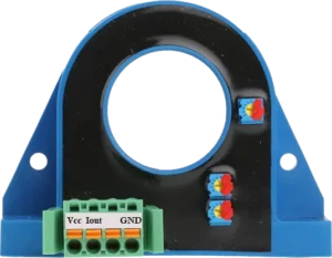
- DHR Pin 1 (Vcc) → +24V DC
- DHR Pin 4 (GND) → Power supply GND
Sensing Current with Arduino and DHR 200 C420
- DHR Pin 2 (Iout) → One end of 220Ω resistor
- The other end of the 220Ω resistor goes to GND
- Tap the voltage across the resistor:
- One side of the resistor → Arduino A0 (analog pin)
- Other side of the resistor → GND
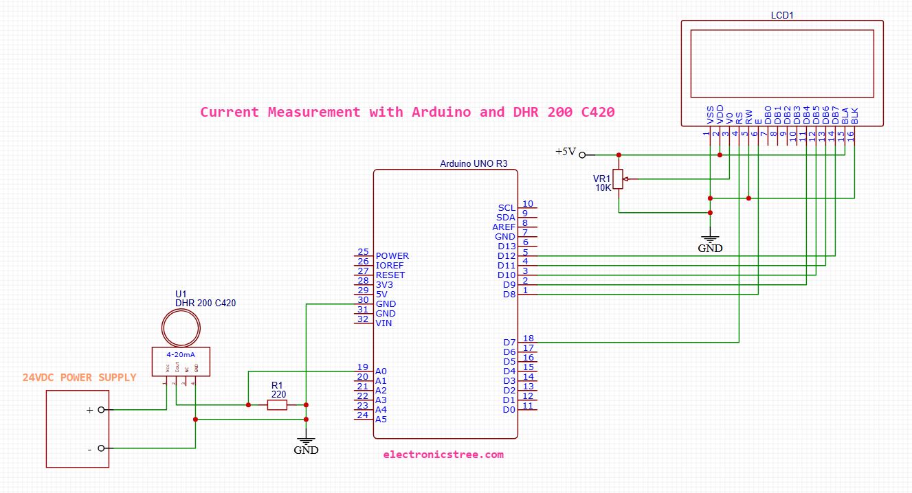
LCD to Arduino Wiring (4-bit mode)
- LCD Pin 1 (GND or VSS) → Connect to Arduino GND
- LCD Pin 2 (VDD) → Connect to Arduino 5V
- LCD Pin 3 (VO) → Connect to the middle pin of a 10k potentiometer
- One side of the pot goes to GND, the other to 5V — this adjusts contrast
- LCD Pin 4 (RS) → Connect to Arduino digital pin 7
- LCD Pin 5 (RW) → Connect directly to GND (we only write to the display)
- LCD Pin 6 (EN) → Connect to Arduino digital pin 8
- LCD Pin 11 (D4) → Connect to Arduino digital pin 9
- LCD Pin 12 (D5) → Connect to Arduino digital pin 10
- LCD Pin 13 (D6) → Connect to Arduino digital pin 11
- LCD Pin 14 (D7) → Connect to Arduino digital pin 12
- LCD Pin 15 (A or LED+) → Connect to 5V
- LCD Pin 16 (K or LED-) → Connect to GND
Arduino and DHR 200 C420 Full Code With LCD Output
- When you call
analogRead(pin), Arduino returns a value from 0 to 1023, based on the input voltage relative to the reference voltage. - The default reference voltage is usually:
- 5V for Uno, Nano, Mega (5V boards)
⚠️ If You Are Powering Arduino via USB
- The 5V rail might be slightly lower than 5V (like 4.8V to 4.95V), which can cause voltage reading errors.
- If accurate measurement is critical, you can:
- Measure the real Vcc with a multimeter and use that instead of
5in the formula
- Measure the real Vcc with a multimeter and use that instead of
voltage = (adcValue / 1023.0) * 4.75;Example: In my case, Vcc is around 4.75V when powering the board via USB.