Electronic dice are a modern twist on traditional dice, using electronic components and circuits to mimic the same function. Typically, these devices feature LEDs (light-emitting diodes) to show the rolled number and buttons to simulate the rolling action.

Electronic Dice Model
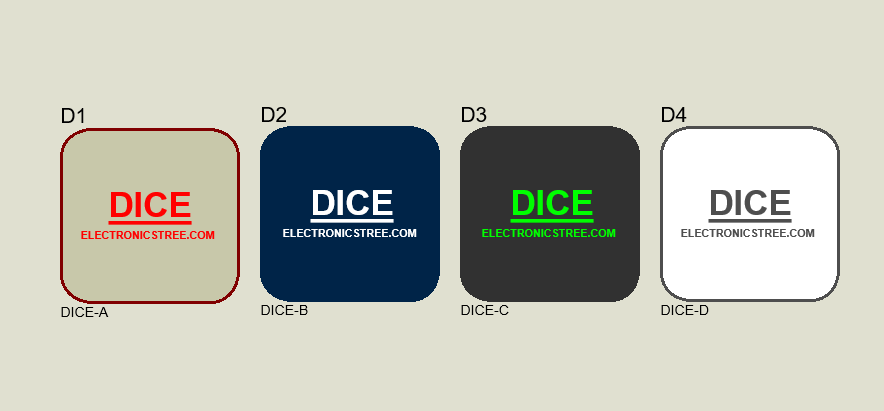
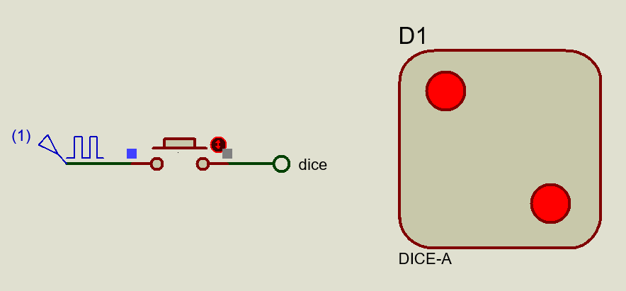
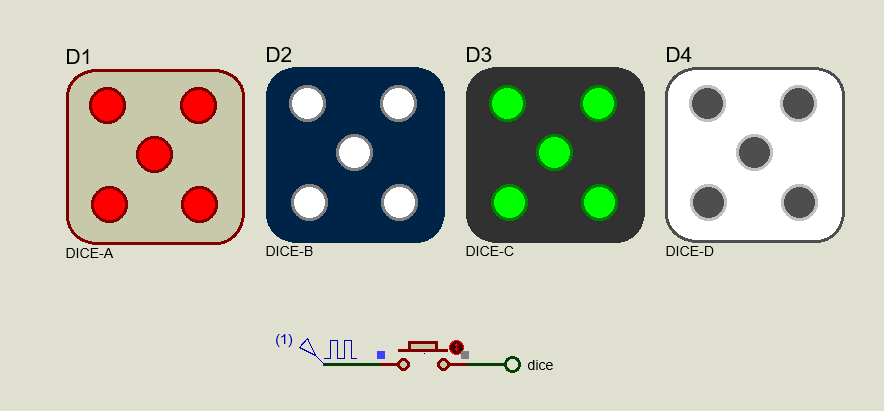
I have designed a dice model library for Proteus projects. This library contains four dice models, each with a different color of dice. Typically, electronic dice work using a microcontroller, LEDs, a button, resistors, and capacitors. The LEDs are arranged in a pattern, often a 3×3 grid, to represent numbers 1 through 6. The microcontroller is responsible for generating random numbers and managing the display.
However, this dice doesn’t need any of these components. Instead, it requires a clock pulse, which you can provide in Proteus in various forms. You can generate the clock signal from the generator mode menu, select the clock device from the device library, or create your own clock source.
How to use Electronic Dice Model
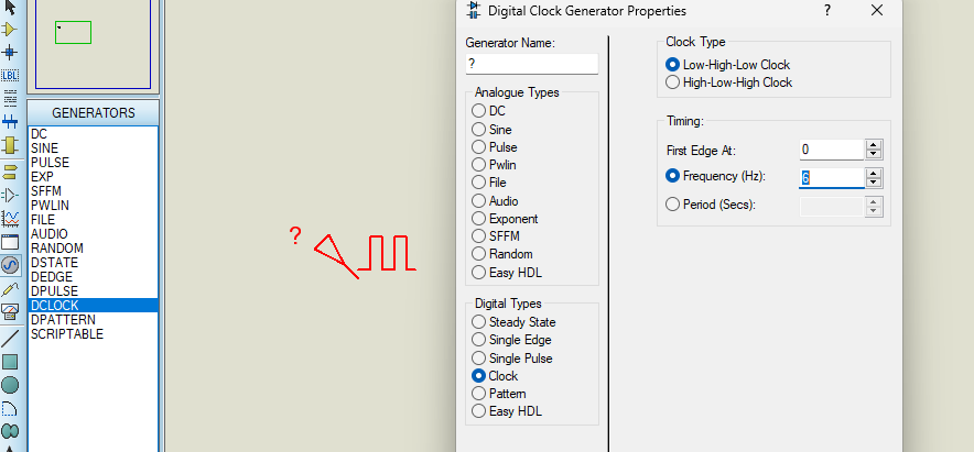
As mentioned earlier, this Electronic dice model only needs a clock source. Let’s select the DCLOCK signal source from the Generator mode toolbar and adjust the frequency to control how quickly the dice roll is simulated. I’ll set it to 6Hz.
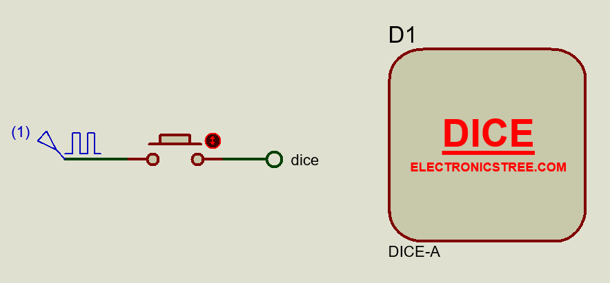
After that, connect it to the button. Now, use the terminal mode toolbar button to select a terminal and connect it to the other side of the button. Name this connection “dice.” Finally, place the dice on the sheet and start the simulation.
Here is the simulation of all dice models available in the library.
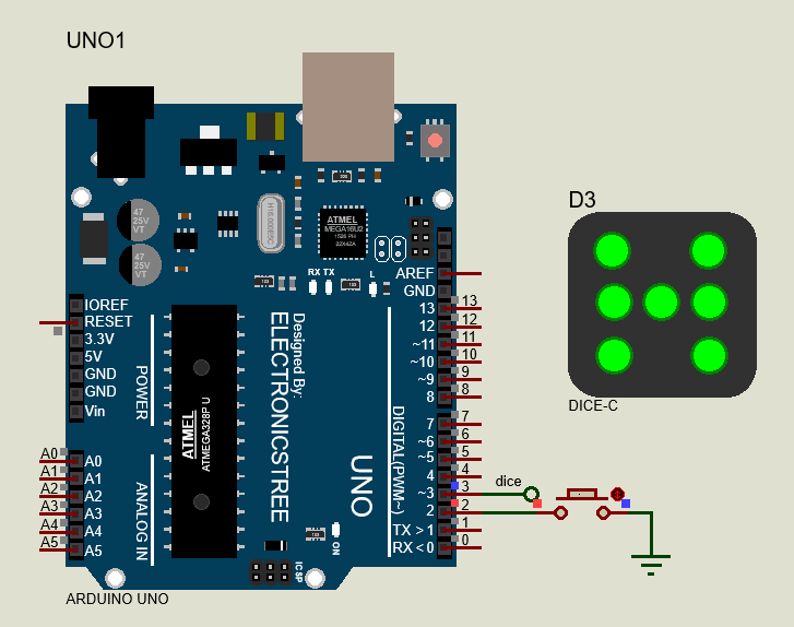
Electronic Dice with Arduino
You can use this Arduino code to make an output pin generate a clock signal when a button is pressed.
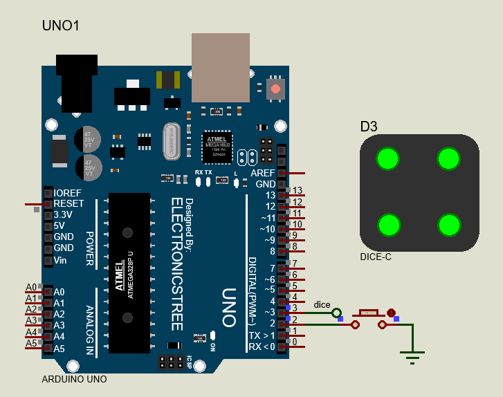
To achieve a 15Hz signal, you calculate the period (T) as 1/15 seconds, approximately 66.67 milliseconds. Each cycle of the signal requires both a HIGH and LOW state, ideally split into halves of around 33 microseconds, considering 1 second equals 1,000,000 microseconds.
In this Arduino example, delayMicroseconds(33) is applied to each half-cycle to achieve the desired 15Hz frequency. This function creates a precise 33-microsecond delay, suitable for generating a 15Hz square wave.
Download Library
Simply click on the button to download the library. You can refer to this post for instructions on how to install the library in Proteus 8. How to Download and install Library in Proteus (electronicstree.com)
ZIP Password : electronicstree.com
If you have any requests for Arduino Module Libraries in Proteus, please leave a comment or message us using the contact form.
