The MPU6050 Proteus Library ZIP file is available for download. This post includes the library and a step-by-step guide on how to use it
When I started working on this MPU6050 simulation model for Proteus, I quickly ran into a fundamental problem: how do you simulate a motion sensor in software? Unlike a temperature sensor where you can just click a marker button to change the temperature value, or an force sensor where you adjust the force level with a marker slider, the MPU6050 measures acceleration and rotation across six different axes, three for the accelerometer (X, Y, Z) and three for the gyroscope (X, Y, Z).
The Challenge
In a real-world scenario, you’d physically hold the MPU6050 board and tilt it, rotate it, or move it around to see how the sensor responds. The accelerometer would detect the direction of gravity and any linear motion, while the gyroscope would measure the rate of rotation. But in Proteus simulation, we don’t have that luxury. We can’t just “pick up” the virtual component and move it around.
The Problem with Direct Axis Control
Proteus has a built-in limitation: by default, it only supports up to three user interface input controls per component. That’s fine for simple sensors, but for an IMU that needs six independent inputs, it’s a dealbreaker. I spent quite a bit of time trying to figure out if there was a way to add more UI controls to a model, but I couldn’t find any method.
The alternative approach would be to expose six separate analog input pins on the component itself. Users would then connect external potentiometers or analog signal generators to each pin to control the individual axis values. While this would technically work, it creates a messy and unintuitive setup. Imagine having to wire up six potentiometers just to test basic MPU6050 functionality, it defeats the purpose of having a quick, easy-to-use simulation model.
There’s also a bigger conceptual problem with direct axis control: it doesn’t match how people actually think about using an IMU. When you’re working with an MPU6050 in a real project, whether it’s a drone, a self-balancing robot, or a motion tracker, you don’t think in terms of “set the X-axis acceleration to 2.5 m/s².” Instead, you think about the physical orientation: “What happens when I tilt the board 30 degrees forward?” or “How does the sensor respond when I rotate it clockwise?
The Solution: Orientation-Based Control
After considering these limitations and usability concerns, I decided to take a different approach. Instead of trying to control six raw sensor values independently, this model uses three orientation angles: Roll, Pitch, and Yaw. These are the same Euler angles used in aviation and robotics to describe the orientation of an object in 3D space:
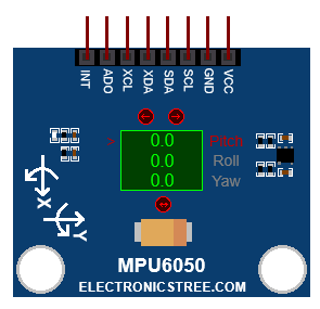
- Roll: Rotation around the X-axis (tilting left or right)
- Pitch: Rotation around the Y-axis (tilting forward or backward)
- Yaw: Rotation around the Z-axis (rotating clockwise or counterclockwise)
With just these three angles, the model can mathematically calculate what the accelerometer and gyroscope readings should be, exactly as if you were physically holding the sensor at that orientation. This approach fits perfectly within Proteus’s three-input limitation and, more importantly, it matches the intuitive way people think about sensor orientation.
When you adjust the Roll angle, the model automatically computes how gravity would be distributed across the X, Y, and Z axes of the accelerometer. When you change the Pitch or Yaw, the model updates both the accelerometer readings (due to gravity’s changing direction) and simulates the corresponding gyroscope values (based on the rate of orientation change).
This orientation-based design makes the simulation much more practical and realistic. Instead of wrestling with six disconnected values, you simply set the sensor’s orientation as if you were physically positioning it in your hand, and the model takes care of generating the correct sensor outputs.
Key Features of the MPU6050 Simulation Model
I²C Slave Interface
The MPU6050 uses the ADO pin to select its I²C address. When ADO is LOW (GND), the I²C address becomes 0x68; when ADO is HIGH (VCC), the address becomes 0x69. The address cannot be changed through Property ( like ADXL345 model ) and is controlled only by the ADO pin, allowing up to two MPU6050 devices to share the same I²C bus.
Sensor Data Generation Mechanism
- Accelerometer outputs simulate static gravity vector projected according to current pitch and roll angles
- Gyroscope outputs simulate angular rates calculated from the rate-of-change of the input angles over simulation time
- Temperature output is fixed or user-defined via property.
- All three axes respect the configured full-scale ranges:
- Accelerometer: ±2 g / ±4 g / ±8 g / ±16 g
- Gyroscope: ±250 °/s / ±500 °/s / ±1000 °/s / ±2000 °/s
- Sensor offset registers are applied to raw outputs (simple additive correction)
Motion Detection & Interrupt System
- Motion interrupt can be enabled via INT_ENABLE register (bit 6 = MOT_EN)
- Detection is based on change in input angles (pitch/roll/yaw) exceeding a small threshold
- When motion is detected → MOT_INT bit (bit 6) is set in INT_STATUS register (0x3A)
- INT pin is driven according to:
- Polarity (active-high or active-low – controlled by INT_PIN_CFG bit 5)
- Latch mode (level or pulse – controlled by INT_PIN_CFG bit 1)
- MOT_THR and MOT_DUR registers are stored (values accepted, but no active duration counter implemented yet)
FIFO Buffer Emulation
- FIFO mode can be enabled via USER_CTRL bit 6
- Selected sensor data (accel, gyro, or both) can be pushed to FIFO based on FIFO_EN register bits
- FIFO count registers (0x72–0x73) are kept updated
- Reading FIFO_R_W register pops oldest data byte-by-byte
- Overflow flag (bit 4 in INT_STATUS) is set when FIFO reaches maximum capacity
Power & Reset Behavior
- Sleep mode (PWR_MGMT_1 bit 6) stops sensor updates when active
- Device reset (via PWR_MGMT_1 bit 7 or USER_CTRL bit 7) returns most registers to default values
MPU6050 Register Coverage Overview
Fully functional (read/write + behavioral effect):
- Who am I register (0x75)
- Power management 1 register (0x6B)
- Sample rate divider register (0x19)
- Configuration register (0x1A)
- Gyroscope configuration register (0x1B)
- Accelerometer configuration register (0x1C)
- Interrupt pin configuration register (0x37)
- Interrupt enable register (0x38)
- Interrupt status register (0x3A)
- Sensor output registers (0x3B–0x48)
- FIFO enable register (0x23), FIFO count high/low registers (0x72–0x73), FIFO read/write register (0x74)
Stored & readable (no behavioral effect):
- Motion threshold register (0x1F)
- Motion duration register (0x20)
- Accelerometer configuration 2 register (0x1D)
- Low-power wake control register (0x1E)
- Motion detection status register (0x68)
- Motion detection control register (0x69)
- Power management 2 register (0x6C)
- All offset registers (0x06–0x18)
Not implemented / ignored:
- I²C master / auxiliary sensor registers (0x24–0x2D)
- Free-fall interrupt registers
- Self-test response registers
- Detailed low-power accelerometer modes
Known Limitations & Simplifications
- No internal digital filters are simulated, raw tilt-derived values are used.
- No free-fall interrupt generation.
- Motion interrupt duration is not actually counted (the motion duration value is stored only).
- Gyroscope and accelerometer standby modes are not implemented (power management 2 settings are stored only).
- No I²C master functionality or external sensor pass-through.
- FIFO overflow stops new writes but does not saturate count.
- Temperature is static (no dynamic thermal simulation).
- No noise or bias drift added (clean synthetic data).
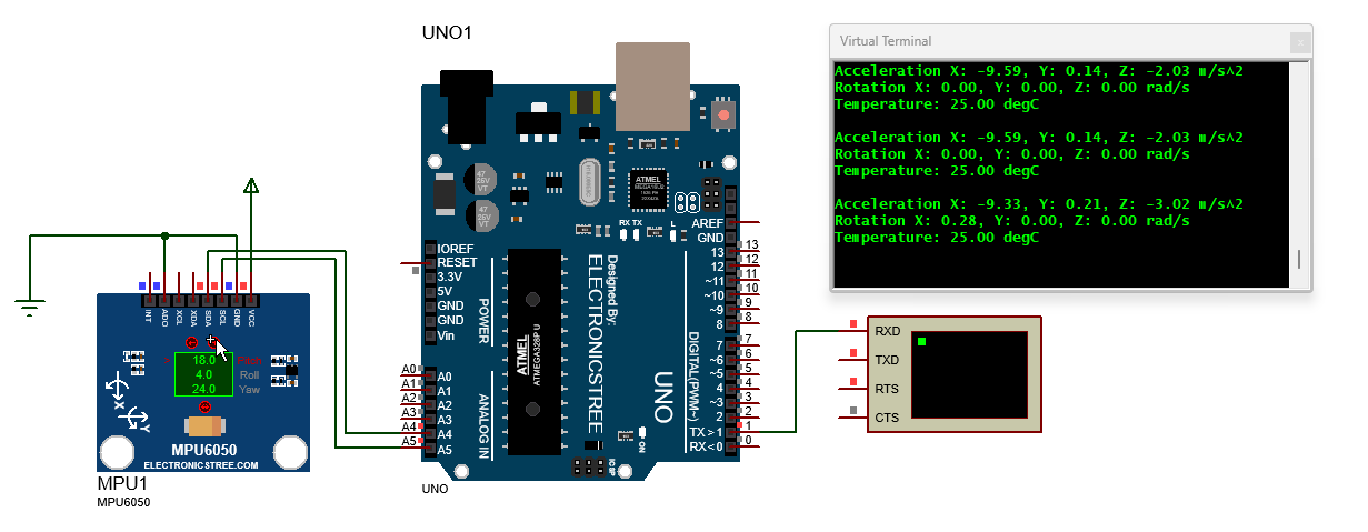
MPU6050 Proteus Simulation
You can easily test the MPU6050 Proteus model using the Adafruit_MPU6050 library in Arduino. Just connect the SDA and SCL pins to your Arduino’s I²C pins. If you want to use interrupts, also connect the INT pin. Then set the pitch, roll, and yaw angles using the input controls.
For basic testing, load the Adafruit basic_readings example sketch and run the simulation. Change the orientation inputs to simulate movement. The sensor registers will update in real time, and you’ll see the acceleration and gyroscope values in the Serial Monitor, just like a real MPU6050. This makes it perfect for testing I²C communication, interrupt handling, range settings, and basic sensor fusion code before you work with actual hardware.
If you want to see larger rotation values or make the MPU6050 readings change faster, you can increase the orientation step size in the model properties. This controls how much the orientation angles change with each input adjustment.
For example:
- Small step size (like 1° or 5°): Good for smooth, precise testing and realistic sensor behavior
- Large step size (like 15° or 30°): Makes the values change quickly and show bigger variations, useful for testing how your code handles rapid movements.
Download Library
Simply click on the button to download the library. You can refer to this post for instructions on how to install the library in Proteus 8. How to Download and install Library in Proteus (electronicstree.com)
ZIP Password : electronicstree.com
We’re always looking to expand our library collection based on what our community needs. If you’re looking for a specific Arduino module, sensor, or component that we don’t currently offer, we’d love to hear from you!
Reach out to us at help@electronicstree.com with your requests. We prioritize new library development based on community demand, so your suggestion could be our next addition.
Fixing the “External model DLL not found (GLE=0x0000007E)” Error
If you start a simulation and see an error message such as:
or something similar with another DLL name, don’t panic. In most cases the DLL is not really missing. What’s happening is that your system doesn’t have the Visual C++ runtime libraries that the DLL needs in order to run.
The solution is simple. Go to Microsoft’s website and download the latest Visual C++ Redistributable for Visual Studio 2015–2022. You can find it here:
During installation, make sure you install both the x86 (32-bit) and x64 (64-bit) versions. Even on a 64-bit system, some applications depend on the 32-bit runtime, so having both installed avoids errors.
Once the installation is complete, restart your computer. After restarting, try running the simulation again. In most cases the error will disappear and everything will work normally.

password error electronicstree.com
It’s working fine
I have tested it again.