1. Introduction
blendixserial is an addon (Extension) that enables real-time serial communication between Blender and external devices or applications through COM ports. Instead of working in isolation, your 3D scene can exchange structured data with microcontrollers, embedded systems, or custom software. You can send and receive data in real time, control 3D objects, and display text from a connected device directly inside Blender. The addon allows you to set up a serial connection, adjust port settings, and switch between different modes depending on your project requirements. The addon supports both a simple CSV format and a custom binary protocol, making it flexible enough for a wide range of technical and creative applications.

2. Features
- Quick Serial Connection – Easily connect and disconnect external devices.
- Real-Time Data Exchange – Send and receive data instantly between Blender and your device.
- Control 3D Objects – Drive and animate objects based on incoming serial data.
- Live Text Display – Show received text as 3D objects in Blender.
- Interactive 3D Viewport Mode (VIM) – Control 3D objects like knobs, buttons, and sliders directly with the mouse.
- User-Friendly Interface – Simple and intuitive panel inside the 3D Viewport.
- Two data formats – Supports CSV format and binary protocol for selective data transmission and reception.
At the heart of the add-on is the use of timers. By registering a function with bpy.app.timers, the add-on makes sure this function runs at regular intervals during the animation process. This gives you precise control over when and how your animations update, allowing for dynamic, automated changes without any manual effort.
This add-on uses Python’s threading and queue modules to manage several tasks at once and pass data smoothly between different parts of the add-on. By handling serial port reading in a separate thread, it keeps receiving data continuously while the Blender scene updates independently. Meanwhile, the queue ensures that each piece of data is processed in the order it was received, preventing any mix-ups or data loss.
3. Interface Overview
3.1 Connection Panel
- Connect / Disconnect
Opens or closes the selected serial port and starts or stops the communication thread. - COM Port
Dropdown list dynamically populated with the available system serial ports. - Baud Rate
Select the communication speed from: 4800, 9600, 19200, 38400, 57600, or 115200. - Connection Status
Displays the current state of the connection: Connected or Disconnected. - Debug Toggle (Console Icon)
Enables or disables debug logging output in Blender’s system console. - About (?)
Opens an information popup displaying the add-on version and related links.
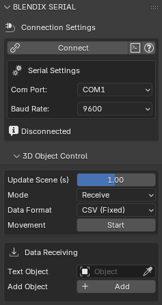
3.2 Object Control Panel
Appears below the Connection Panel as a sub-panel.
- Update Scene (s)
Timer delay slider that controls how frequently the scene updates. - Mode
Select Send, Receive, or Both. Determines which serial thread operations are active. - Data Format
Choose between CSV (Fixed) and Protocol (Selective). - Start / Stop
Pauses or resumes object movement without disconnecting the serial port.
When Both mode is selected, a tab row appears allowing you to switch between the Receive and Send views.
3.2.1 Receive Tab
- Text Object
Select a FONT object used to display incoming text data. - Add Object
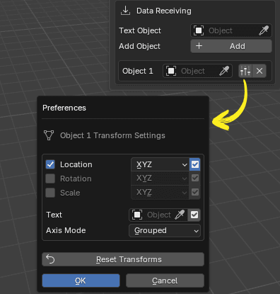
Adds a new row to the Receive collection.- Per-Row Controls
Each row includes:- An object picker
- A settings popup (axes configuration and text overlay options)
- A remove button
- Settings Popup
Allows you to:- Enable or disable Location, Rotation, and Scale per axis
- Link a FONT object for text display
- Set the axis display mode to GROUP or AXIS
- Per-Row Controls
3.2.2 Send Tab
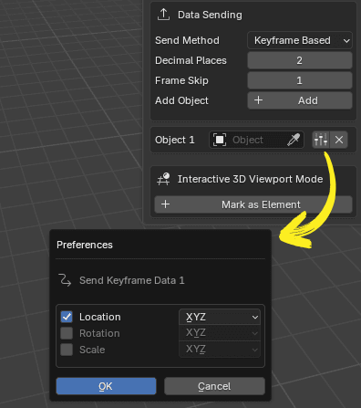
- Send Method
Choose between Keyframe (Frame Change) or Timer to control when data is transmitted. - Decimal Places
Sets the precision for CSV float output (range: 0–6). - Frame Skip
Defines how often data is sent in frame-based mode.
A value of 0 sends data every frame; otherwise, data is sent every N frames. - Add Object
Adds a new row to the Send collection.- Per-Row Controls
Each row includes:- An object picker
- A send settings popup (select which axes to transmit)
- A remove button
- Per-Row Controls
4. Viewport Real-time VS Final Real-time
Real-time rendering lets you see and interact with your scene smoothly in the 3D viewport. It focuses on speed by using simpler graphics and lower-quality textures. This helps keep performance fast. Final rendering, on the other hand, creates high-quality images or videos with detailed lighting, shadows, and textures. It takes more time and processing power but gives a more realistic result.
The blendixserial addon uses a timer-based technique to animate objects within the scene. This technique involves registering a timer that calls a specific function repeatedly at regular intervals. In this case, a specific function is registered with bpy.app.timers to automate actions and updates in the scene. By utilizing timers, the addon can control the timing and frequency of object movements or other changes.
In the viewport, you can adjust the update scene delay and optimize the scene to achieve a smooth real-time display. By reducing the update scene delay, you can increase the frequency at which the scene is updated, resulting in smoother motion and a closer representation of real-time. However, when it comes to final rendering for videos or images, achieving real-time rendering in the strictest sense, which means rendering an entire frame within the time it takes to display that frame, may not be possible. You can test this feature in the final real-time rendering process, and if you succeed, I would appreciate it if you could share your results with me as well.
5. Object Handling Capacity
The blendixserial add-on is designed to dynamically manage objects through custom collections, offering flexibility when working with different objects. There’s no hard cap on the number of objects the add-on can handle, its limits are really determined by your system’s performance and the speed of the serial communication
Note that I’ve only tested the add-on with 10 objects, so performance with larger numbers has not been fully explored.
Blender itself is capable of managing thousands of objects, but how well it performs depends on several factors. These include the power of your CPU and GPU, the complexity of the scene (like the number of polygons or animations), and how responsive the user interface is.
The speed of the serial communication is another key factor. Slower baud rates, like 9600-38400 bps, work fine for handling a smaller number of objects. But if you’re working with more objects and need faster updates, higher baud rates (115200+ bps) are the way to go.
6. Interactive Viewport Mode (VIM)
6.1 What is VIM?
VIM (Interactive Viewport Mode) is a feature in blendixserial that lets you click and drag 3D objects in Blender’s viewport to simulate physical controls, like turning a knob, pressing a button, or moving a joystick, and automatically stream those values to a connected device over serial in real time. Your 3D object becomes a virtual control panel. Whatever you do to it in Blender gets sent to your Arduino, ESP32, or any serial device immediately.
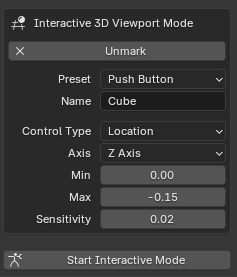
6.2 How It Works
VIM adds custom properties to any object you “mark”. These define how the object should behave, what it controls (rotation, location, or scale), which axis, the value range, and sensitivity. When you click Start Interactive Mode, a modal operator takes over the viewport. It listens for mouse input, updates the object’s transform, and the normal send pipeline transmits those values over serial.
Mouse drag → Modal operator → Object transform → Send pipeline → Serial out6.3 How to Use VIM
- Set Mode to
SendorBothin the 3D Object Control panel - Select the 3D object you want to use as a control
- In the Send tab, scroll to Interactive 3D Viewport Mode → click Mark as Element
- Choose a Preset from the dropdown (settings auto-fill)
- Add the same object to the Send list above and enable the axes to transmit
- Connect your serial port and click Start under Serial Comm
- Click Start Interactive Mode at the bottom of the Send tab
- Click and drag the object in the viewport, values update live and are sent over serial
Press ESC or Right Mouse Button to exit Interactive Mode.
6.4 How Each Control Type Behaves
- Rotation
Drag the mouse in a circular motion. The system calculates the angular difference between mouse positions relative to the object’s center. - Location / Scale
Drag along a specific axis. The movement generates a linear delta — horizontal movement controls the X axis, while vertical movement controls the Y and Z axes. - Joystick 2D
Drag in any direction. The movement delta is mapped to the view’s right and up vectors and then projected onto the object’s local XY plane. - Binary
Triggered by clicking.- Momentary: value is 1 while pressed and 0 when released.
- Latching: value toggles between states with each click.
6.5 Important Note About Sending
VIM does not have its own send system. It simply updates the object’s Blender transform. The normal send pipeline picks up those values and transmits them. The object must also be in the Send list with the correct axes enabled, otherwise VIM moves it visually but nothing goes over serial.
7. Communication Modes
The blendixserial addon supports two completely different communication formats, referred to as modes. The first is CSV Mode, which encodes all data as plain human-readable text using commas and semicolons. The second is Protocol Mode, which encodes data as a structured binary packet with a fixed framing scheme and a checksum for error detection. Both modes use exactly the same underlying serial connection and background thread, and both support the same send trigger options and the same object mapping system. The only thing that changes between the two modes is the actual bytes that travel over the wire and the way those bytes are assembled and interpreted on both ends
7.1 CSV Mode
CSV Mode is the simpler of the two communication formats. Every message is a single line of plain ASCII text, making it readable and writable with nothing more than a serial monitor or a few lines of Serial.print() calls on an Arduino.
7.1.1 What a CSV Message Looks Like
A CSV message is built from two optional sections separated by a semicolon character. The section before the semicolon contains numerical data: one or more floating-point numbers separated by commas. The section after the semicolon contains text data: an arbitrary string. Either section can be empty, but at least one must be present for the message to be useful. The message is terminated by a newline character, which is added automatically by the addon when sending.
The simplest possible CSV message is a list of nine numbers followed by a semicolon, representing the full transform of one Blender object. A more complex message might contain eighteen numbers (two objects) or nine numbers plus a status string. A text-only message starts with a semicolon directly, with nothing before it, and contains only the text string after it.
FORMAT EXAMPLES
Numbers only:     1.50,90.00,0.00,0.00,0.00,0.00,1.00,1.00,1.00;
Numbers + text:   1.50,90.00,0.00,0.00,0.00,0.00,1.00,1.00,1.00;STATUS_OK
Text only:        ;ALERT: sensor overflow
Two objects:      obj0_v0,...,obj0_v8, obj1_v0,...,obj1_v8;
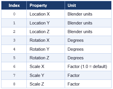
7.1.2 The Nine-Value Layout
When addon sends the transform data of a object in CSV Mode, it always produces exactly nine comma-separated values, regardless of how many axes are actually enabled in the send settings. Axes that are disabled receive a value of 0.00. The positions of the nine values are fixed and must be respected by both sender and receiver:
It is worth noting that Blender stores rotation internally in radians, but the addon converts to degrees before sending. This means the hardware always receives rotation values in the human-intuitive degree scale. If you rotate a cube 90 degrees around the Z axis in Blender, the value at index 5 in the outgoing CSV message will be 90.00, not 1.5707. The reverse conversion happens automatically on receive
7.1.3 Multi-Object CSV Messages
When multiple objects are added to the Send Objects list in the addon panel, the addon formats each one using the nine-value layout described above and joins all the blocks together with a comma and space separator. A single semicolon is appended at the very end. The result is one long comma-separated line that encodes all objects in sequence.
For example, if two objects are in the Send Objects list, the message will contain eighteen comma-separated values followed by a semicolon. The first nine values belong to the first object in the list and the next nine to the second. There is no per-object label or separator inside the CSV message, the hardware receiver must know in advance how many objects to expect and read nine values at a time, using the object’s position in the list as a stride.
This flat layout is a significant limitation of CSV Mode compared to Protocol Mode. If the receiver is not aware of how many objects are being sent, it has no way to determine where one object’s data ends and the next begins. Protocol Mode solves this by including an explicit object count and per-object identifier in every packet.
7.2 Protocol Mode
When the blendixserial addon is set to Protocol Mode, every message sent or received over the serial connection is encoded as a self-contained binary packet. Unlike CSV Mode, where data is plain text that you can read directly in a serial monitor, a Protocol Mode packet is a sequence of raw bytes that must be parsed according to a defined structure. In return for that extra complexity, Protocol Mode is significantly more efficient, more precise, and far more robust against data corruption than text-based communication.
Every Protocol Mode packet has the same outer envelope regardless of what data it carries: a fixed start marker, a compact header that describes the packet’s contents, a variable-length payload that holds the actual data, a checksum byte for error detection, and a fixed end marker. This structure is sometimes called a framed binary protocol because the start and end markers form a visible frame around the data.
The following diagram shows the byte-by-byte layout of a complete packet. Each coloured region corresponds to one logical section, which is described in full in the sections that follow.
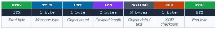
The minimum possible packet is 7 bytes: a 5-byte header with a payload length of zero, one checksum byte, and one end marker byte. In practice every useful packet is larger because an empty payload carries no data. The maximum theoretical packet size is 5 + 65535 + 2 = 65542 bytes, dictated by the 16-bit payload length field, though no realistic Blendix use case comes close to that limit.
7.2.1 The Header (5 Bytes)
The header is the fixed-length opening section of every packet. It is always exactly 5 bytes and always appears in the same order. The header’s job is to allow the receiver to identify the start of a packet, understand what kind of data follows, and know precisely how many bytes of payload to read before looking for the checksum and end marker.
Byte 0 | STX (Start of Transmission)
The very first byte of every packet is always the fixed value 0x02. This value comes from the ASCII control character called STX, which stands for Start of Text. Its sole purpose is to mark where a packet begins.
Serial communication is a continuous stream of bytes with no natural gaps between packets. When a receiver first powers on, it has no idea where in the stream it is, it might be looking at the middle of a packet, or at garbage bytes from electrical noise, or at a completely valid packet start. The STX byte solves this problem by giving the receiver a recognisable landmark to aim for. The receiver simply discards bytes one at a time until it sees 0x02, then treats the next byte as the start of the header
This process is called synchronization or re-sync. The same re-sync logic also kicks in whenever something goes wrong mid-stream, for example, if a packet is corrupted and the checksum does not match, the receiver discards the STX and starts scanning forward again for the next 0x02. Because only one byte is discarded at a time, recovery is fast and the receiver typically re-syncs within one or two bytes.
Byte 1 | Message Type
The second byte tells the receiver what kind of data the payload contains. It can take one of three values, each corresponding to a different payload structure. The receiver must read this byte first before attempting to parse anything else, because the structure of the payload is entirely different depending on this value.
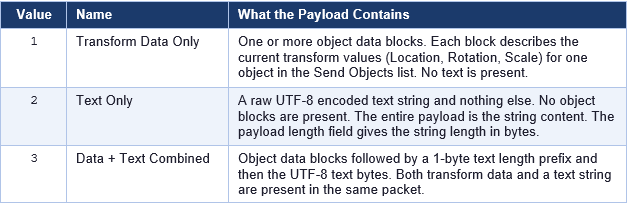
In everyday blendixserial usage, message type 1 is by far the most common, it is what the addon sends every time the send trigger fires and there are objects in the Send Objects list with at least one axis ticked. Message type 2 is available when you want to send only a text string to the hardware with no transform data. Message type 3 lets you bundle both together in one packet, which saves the overhead of sending two separate packets when you always need both.
The msg type byte is also part of the checksum calculation, which means any corruption that changes this byte will be detected and the packet will be discarded rather than parsed as the wrong type.
Byte 2 | Object Count
The third byte holds the number of object data blocks that appear in the payload. The receiver uses this count to drive its parsing loop: it reads exactly object count blocks from the payload, then stops and moves on to the text segment if one is expected.
This count reflects how many objects in the Send Objects list in the blendixserial panel have at least one transform axis ticked. If you have five objects in that list but only three of them have any Location, Rotation, or Scale axes enabled, object count will be 3 and only three blocks appear in the payload. Objects with no ticked axes contribute nothing to the packet.
For message type 2 (text only), this byte is always 0 because there are no object blocks in the payload at all. For message types 1 and 3, it is a value from 1 to 255. The fact that it is a single unsigned byte limits Protocol Mode to a maximum of 255 objects per packet, which is more than sufficient for any practical blendixserial use case.
The msg type byte is also part of the checksum calculation, which means any corruption that changes this byte will be detected and the packet will be discarded rather than parsed as the wrong type.
Bytes 3–4 | Payload Length
The fourth and fifth bytes of the header form a 16-bit unsigned integer, transmitted in big-endian order (most significant byte first), that holds the total length of the payload section in bytes. This is the number of bytes the receiver must read after the 5-byte header before it reaches the checksum byte and the end marker.
Having an explicit length field is what makes this a length-delimited protocol rather than a delimiter-delimited protocol. In a delimiter-delimited protocol (like CSV Mode’s newline termination), the receiver reads until it hits a specific byte value that signals the end. In a length-delimited protocol, the receiver reads exactly as many bytes as the header says to, with no need to scan for a special byte. This is faster, more reliable, and means any byte value can appear in the payload without ambiguity.
The length is encoded in big-endian order, the byte at position 3 holds the high 8 bits and the byte at position 4 holds the low 8 bits. The maximum value this field can represent is 65535, giving a maximum payload of 65535 bytes. In practice, blendixserial packets are rarely more than a few dozen bytes.
The payload length includes every byte of the payload, all object blocks and any text segment, but does not include the checksum byte or the end marker. So the total packet length in bytes is: 5 (header) + payload_len + 1 (checksum) + 1 (end marker) = payload_len + 7.
7.2.2 The Payload: (Variable Length)
The payload is the variable-length section of the packet that carries the actual data. Its internal structure depends entirely on the msg type value in the header. For message type 1 the payload is nothing but object data blocks. For message type 2 it is nothing but a UTF-8 text string. For message type 3 it is object data blocks followed by a text segment. This section explains each case in full.
Object Data Block Structure
For message types 1 and 3, the payload opens with one object data block per object. The blocks are packed back-to-back with no padding or separators between them. The receiver reads exactly object count blocks using the count from the header. Each block has three parts: an object index, a bitmask, and a variable-length array of float values. The structure is deliberately compact, only the bytes that carry actual information are present, nothing more.
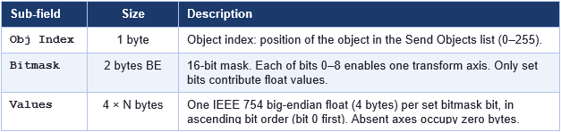
Object Index | 1 byte
The first byte of every object block is the object’s index number. This is a zero-based position that corresponds directly to the order of objects in the Send Objects list in the Blendix panel. The first object in the list has index 0, the second has index 1, the third has index 2, and so on, up to a maximum of 255.
On the hardware side, this index number is how you know which physical component to update. If index 0 drives servo motor 0 and index 1 drives servo motor 1, your firmware reads this byte first and uses it as an array index or switch statement to dispatch the values to the correct motor. This means you do not have to rely on the order of blocks in the payload, even if the packet contains three objects, you can safely process them in whatever order they arrive by reading the obj id or index of each block first.
The index is also stable across packets: as long as you do not reorder the Send Objects list in the Blendix panel, the same object will always appear with the same index, making firmware logic straightforward to maintain.
Bitmask | 2 bytes big-endian
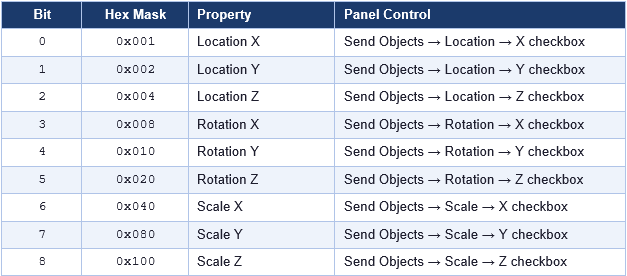
The next two bytes form a 16-bit unsigned integer in big-endian order that acts as a compact map of which transform axes are included in this block’s float values. Blendix uses 9 of the 16 available bits, one for each of the nine transform axes (three for Location, three for Rotation, three for Scale). The remaining bits 9 through 15 are always zero and should be ignored.
The key principle is that a set bit (1) means the corresponding axis value is present as a float in the values array that follows. A cleared bit (0) means that axis is not present, no bytes for it appear in the values array at all. This is called sparse encoding because the packet only contains the axes that are actually needed, skipping all the rest. It is what makes Protocol Mode significantly more bandwidth-efficient than CSV Mode, which always sends all nine values regardless of how many are actually in use.
Example:  bitmask = 0x0025  (binary: 0000 0000 0010 0101)

Bits set:  bit 0 (0x001) = Location X
           bit 2 (0x004) = Location Z
           bit 5 (0x020) = Rotation Z

Values array contains exactly 3 floats in this order:
  float 0 → Location X value
  float 1 → Location Z value
  float 2 → Rotation Z value

Total bytes for this block: 1 (obj_id) + 2 (bitmask) + 12 (3 floats × 4) = 15 bytes.
The bits are consumed in ascending order: if bits 0, 3, and 6 are set, the values array contains three floats, first the float for bit 0 (Location X), then the float for bit 3 (Rotation X), then the float for bit 6 (Scale X). On the receiver side you must read the bitmask first and then iterate through bits 0 to 8 in order, reading a float only for each set bit and advancing your read pointer by 4 bytes each time. If a bit is not set you do not advance the pointer, there is simply no byte there.
The table below shows the exact mapping between each bitmask bit and the blendixserial panel control that enables it.
Values | Float Array, 4 bytes per set bit
After the bitmask comes the actual numerical data: one IEEE 754 single-precision float for every bit that is set in the bitmask, in ascending bit order. Each float occupies exactly 4 bytes, encoded in big-endian order (most significant byte first).
IEEE 754 single-precision is the standard 32-bit floating-point format used by C’s float type, Python’s struct ‘>f’ format string, and virtually every programming language and hardware platform. It provides approximately 7 significant decimal digits of precision and can represent values from roughly 1.2 × 10⁻³⁸ to 3.4 × 10³⁸, which is more than sufficient for Blender’s coordinate system.
The big-endian byte order means the most significant byte comes first. On a little-endian platform such as Arduino (AVR or ARM), you must reverse the four bytes before interpreting them as a float. The correct approach is to copy the four bytes into a temporary array in reverse order and then use memcpy to reinterpret those bytes as a float, as shown in the Arduino examples in this explanation.
Rotation values are always in degrees, not radians. Blender stores rotation internally as radians, but Blendix converts to degrees before encoding the float. This means the hardware always works in the human-intuitive degree scale. A 90-degree rotation will arrive as the float 90.0, not 1.5707963.
Text Segment | Msg type 2 and 3
The text segment carries an arbitrary UTF-8 encoded string. Where it appears in the payload and how its length is communicated differs between message type 2 and message type 3.
Message Type 2 - Text Only
When msg type is 2, the entire payload is raw UTF-8 bytes and nothing else. There is no length prefix inside the payload because the payload length field in the header already tells the receiver exactly how many bytes to read. The receiver reads payload length bytes and decodes them as a UTF-8 string. The maximum string length for message type 2 is 65535 bytes, which is the maximum value the 2-byte payload length field can represent.
This message type is used when the hardware needs to send a text string to Blender, for example, a status message, an error code, or a sensor label, without any accompanying transform data. On the blendixserial receive side, the text string is written to the Blender Text object assigned to the Received Text slot in the blendixserial panel.
Message Type 3 - Data and Text Combined
When msg type is 3, the payload contains both object data blocks and a text string in the same packet. The object blocks come first, as described in Section 6.2.1. After the last object block, the text segment begins, but here, unlike message type 2, a 1-byte unsigned integer appears before the text bytes. This byte holds the length of the text string in bytes.
This extra length prefix is necessary because the receiver has just finished parsing a variable number of variable-length object blocks. At that point it is somewhere inside the payload at an unknown offset, and it needs to know how many bytes of text to read before it reaches the end of the payload. The 1-byte prefix provides exactly that information. Because it is only 1 byte, the maximum text length in a type-3 message is 255 bytes. If you need to send a longer string alongside transform data, you would need to split the message into a type-1 packet followed by a separate type-2 packet.
Message type 3 is currently prepared in the blendixserial codebase but the text portion is always an empty string in normal operation. The receive side fully supports parsing all three message types.
7.2.3 The Checksum (1 Byte)
Immediately after the last byte of the payload, before the end marker, comes a single checksum byte. Its purpose is to allow the receiver to verify that the packet was not corrupted during transmission. If even one bit in the packet flips due to electrical noise, electromagnetic interference, or a loose cable, the checksum will not match and the entire packet is discarded rather than silently applied to the scene with wrong values.
How the Checksum Is Calculated
The checksum is computed using the XOR (exclusive-or) operation applied to every byte in the packet except the STX byte at the start and the ETX byte at the end. In other words, it covers: msg type, object count, the two payload length bytes, and every payload byte from the first to the last.
XOR has a useful mathematical property: XOR-ing any value with itself produces 0, and XOR-ing any value with 0 leaves it unchanged. This means the order in which you XOR the bytes does not matter, and XOR-ing all the covered bytes together produces a single result byte that is sensitive to changes in any of those bytes. If any covered byte is different on the receive side, the XOR result will be different from the transmitted checksum, and the mismatch is detected.
What the Checksum Can and Cannot Detect
An XOR checksum reliably detects any single-bit error anywhere in the covered bytes. It also detects many multi-bit errors. However, it cannot detect all multi-bit errors, specifically, if two bits that happen to be in the same position across different bytes both flip simultaneously, they cancel each other out in the XOR and the checksum remains the same. This is an inherent limitation of single-byte checksums.
7.2.4 The End Marker (1 Byte) ETX
The final byte of every packet is always the fixed value 0x03. This value comes from the ASCII control character called ETX, which stands for End of Text, and it is the pair to the 0x02 STX byte at the start
After reading the payload and the checksum, the receiver checks that the next byte is 0x03. If it is not, for example, because the payload length field was corrupted and caused the receiver to consume more or fewer bytes than the actual payload, this check will fail. The receiver then discards the starting 0x02 and begins re-syncing. This makes the ETX byte a second layer of sanity checking on top of the checksum: even if a freak multi-bit error somehow produced a matching XOR checksum, an incorrect ETX position would still catch the problem.
Like the STX byte, the value 0x03 can appear naturally inside the payload (as part of a float encoding). This is not a problem because the receiver only checks for 0x03 at the specific byte position given by the total packet length formula, not by scanning the entire buffer for 0x03.
8. Requirements
This addon has been migrated to Blender’s new Extensions platform, which means it requires Blender 4.2 or newer. If you are using Blender 4.2 or later, you can install it directly as an extension. However, if you are using an older version of Blender, you will need to download and use blendixserial v0.12 from GitHub, as that version is compatible with earlier Blender releases.
9. blendixserial Installation
- Open Blender and go to Edit -> Preferences.
- In the Preferences window, click on the Get Extensions tab.
- In Extension tab click the down arrow button at the top-right corner and select “install from disk”.
- Browse and select the blendixserial zip file. The add-on is now installed and ready to use.
Serial Module
'serial' module, which is needed for serial communication, isn’t installed or accessible in your Blender environment.
Manual Installation
serial module pre-installed, you’ll need to install it manually. Here’s how to fix it:- Download the ‘serial’ module package from the Python Package Index (PyPI) website.
- Once it’s downloaded, unzip the package and find the ‘serial’ folder.
- Copy the ‘serial’ folder.
- Go to your Blender installation directory, locate the “modules” folder, and paste the ‘serial’ folder there.
- After that, enable the add-on again.
Now, you should be able to use blendixserial in Blender
Auto Installation
Instead of installing the serial module manually, blendixserial can install it automatically. You only need to run Blender as an administrator. The addon will then download and install the required serial module into Blender’s Python directory automatically. After that, everything works without any manual setup.
The only downside is that you must run Blender as an administrator every time. If you start Blender normally (without administrator privileges), the addon will not work properly because it does not have permission to access or install the required module.
10. License
This Addon is distributed under the terms of the GNU General Public License version 3 (GPLv3). You are free to redistribute and modify this program in compliance with the terms of the license. For more details, refer to the GNU General Public License page.